
Multi-layer circuit board having at least two or more circuit patterns connected

a multi-layer circuit board and circuit pattern technology, applied in the direction of circuit inspection/indentification, electrical connection formation of printed elements, improvement of metal adhesion of insulating substrates, etc., can solve the problem of fluctuation of connection resistance, insufficient application of pressure to the central portion of the substrate, and insufficient compression of conductive pas

Inactive Publication Date: 2004-03-02
PANASONIC CORP
View PDF13 Cites 4 Cited by
  • Summary
  • Abstract
  • Description
  • Claims
  • Application Information

AI Technical Summary

Benefits of technology

"The present invention relates to a multi-layer circuit board and a method of manufacturing it. The technical effect of the invention is to provide a method for making inner via-hole connections between circuit patterns in a multi-layer circuit board that is reliable and has a high-density structure. The method involves a process for manufacturing a double-side circuit board with four layers, which involves bonding layers together using a laser beam machining process and then adding conductive paste to the bonded layers. The resulting circuit board has reliable inner via-hole connections and highly dense circuit patterns."

Problems solved by technology

However, due to variation in quantity and fluidity of the resin contained in the prepreg sheet, the peripheral resin excessively flows during heating under pressures, resulting in insufficient application of the pressure to the central portion of the substrate, and accordingly, the conductive paste will not be sufficiently compressed.
As a result, there has been a problem of fluctuation in connection resistance.

Method used


Image

  • Multi-layer circuit board having at least two or more circuit patterns connected
  • Multi-layer circuit board having at least two or more circuit patterns connected
  • Multi-layer circuit board having at least two or more circuit patterns connected

Examples


exemplary embodiment 2

The second exemplary embodiment of the present invention for a method of manufacturing a circuit board will be described in the following.

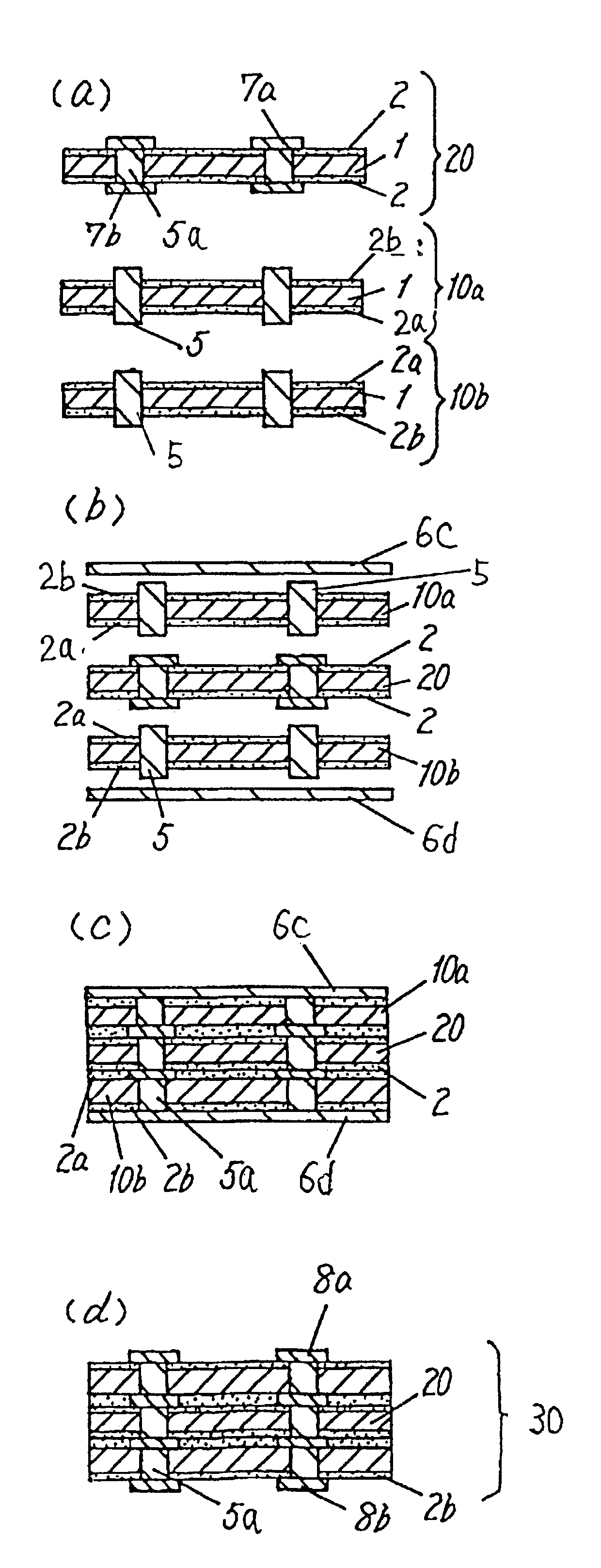
FIG. 5 is a sectional view of the process showing a method of manufacturing a multi-layer circuit board in the present exemplary embodiment, and the multi-layer circuit board has four layers of circuit patterns.

In FIG. 5(a), first double-side circuit board 20a, second double-side circuit board 20b, and insulating substrate 10 are prepared. These double-side circuit boards 20a, 20b are same in configuration as the double-side circuit board 20 manufactured in the first exemplary embodiment described above.

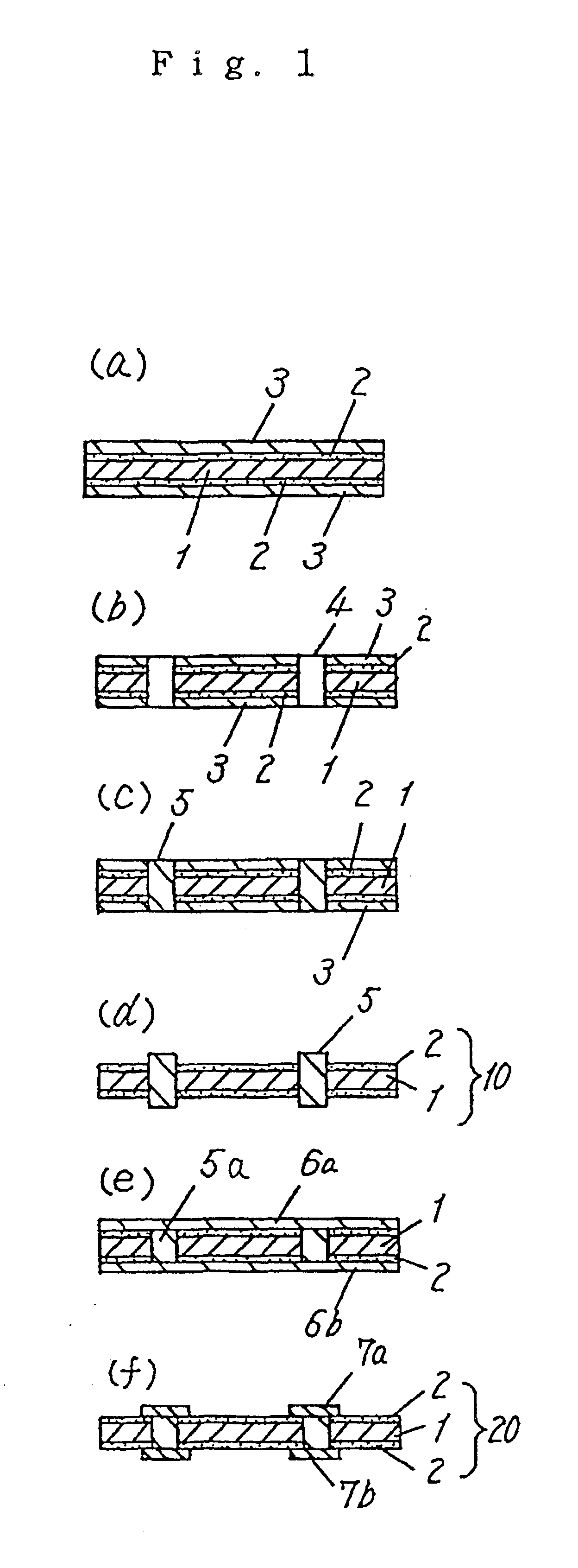
Intermediate substrate 10 is same in configuration as the intermediate substrate 10 manufactured in the first exemplary embodiment described above. That is, the intermediate substrate 10 comprises the incompressible substrate 1, bonding layers 2a, 2b disposed on either side of the substrate 1, and conductive paste 5 disposed in the through-hole. Th...

exemplary embodiment 3

The third exemplary embodiment of the present invention for a method of manufacturing a circuit board will be described in the following.

FIG. 6 is a sectional view of the process showing a method of manufacturing a multi-layer circuit board in an exemplary embodiment, and the multi-layer circuit board has four-layer circuit patterns.

As shown in FIG. 6(a), double-side circuit board 20, first bonding substrate 30a, and second bonding substrate 30b are prepared. As the double-side circuit board 20, a double-side circuit board 20 same as the double-side circuit board 20 manufactured in the first exemplary embodiment is employed. The double-side circuit board 20 comprises substrate 1, bonding layers 2 disposed on either side of the substrate 1, first circuit pattern 7a and second circuit pattern 7b bonded thereto by the bonding layer 2. Each of the circuit patterns 7a, 7b is about 12 .mu.m in thickness. The first circuit pattern 7a and the second circuit pattern 7b are electrically conne...


PUM

PropertyMeasurementUnit
thicknessaaaaaaaaaa
thickaaaaaaaaaa
thicknessaaaaaaaaaa

Abstract

A circuit board having stable connection resistance can be obtained . The multi-layer circuit board includes the steps of making through-holes in a incompressible substrate having films on either side thereof via a bonding layer; filling conductive paste into the through-holes; removing the films from the substrate; laminating metallic foils to either side of the substrate and heating same under pressures to harden the bonding layer, bonding the metallic foils to the substrate and electrically connecting the sides of the substrate to each other; and forming a circuit pattern by machining the metallic foils.

Description

The present invention relates to a multi-layer circuit board with at least two or more layers of circuit patterns connected, and a method of manufacturing same.BACKGOUND OF THE INVENTIONWith a recent trend of electronic equipment becoming more miniaturized and higher in component density, there is an increasing demand for multi-layered circuit boards in the fields of both industrial and home-use equipment.In the field of such multi-layer circuit board, there is a strong demand for the development of a method of making inner via-hole connection between multi-layered circuit patterns, and a circuit board having a highly reliable structure. As a method of manufacturing such circuit board, Japanese Laid-open Patent No. 6-268345 is proposing a method of manufacturing a high density circuit board having a novel structure wherein inner via-hole connections are made by conductive paste. This conventional method of manufacturing a circuit board will be described in the following.A method of ...

Claims


Application Information

Patent Timeline
Patent Type & Authority Patents(United States)
IPC IPC(8): H05K3/40H05K3/46H05K3/38H05K1/02H05K1/11H05K1/03H05K3/00
CPCH05K3/4069H05K3/462H05K1/0268Y10T29/49155H05K3/4652H05K2201/0195H05K2201/0355H05K2201/10378H05K2203/0191H05K2203/066H05K2203/1461Y10T29/49117Y10T29/49126Y10T29/49165H05K3/386
Inventor TAKENAKA, TOSHIAKINISHII, TOSHIHIROYAMANE, SHIGERUNAKAMURA, SHINJIKOMODA, HIDEAKIKISHIMOTO, KUNIO
Owner PANASONIC CORP
Learn More