Flexure hinge

a technology of flexure hinges and hinges, applied in the field of flexure, can solve the problems of reducing strength with respect to normal stresses, bending stiffness, and inability to meet the demands of use, and achieve the effect of reducing production and calculation, and contributing to the stability of the hing

Active Publication Date: 2018-05-08
WIPOTEC GMBH
View PDF31 Cites 1 Cited by
  • Summary
  • Abstract
  • Description
  • Claims
  • Application Information

AI Technical Summary

Benefits of technology

[0022]In a manner different from leaf springs, which do have a constant thickness, but have an undefined point of rotation, the point of rotation in the case of the embodiment aimed at the area equivalent continues to be defined at the site of the least thickness or the least moment of resistance. As a result, in this variation the responsiveness of a balance could be increased by 20% through the reduction of the bending stiffness, while keeping the hinge thickness and strength the same.
[0028]Preferably, the flexure hinge is provided with a plurality of recesses, which lie side by side in width direction Z. This results in a uniform stress distribution over the viewed section width B. Expediently, the recesses have the same shape, which simplifies production and calculation. Moreover, the recesses preferably have the same spacings from each other in the Z direction, which distributes stresses still more uniformly over the width of the hinge.
[0029]One embodiment of the invention provides that all recesses are spaced a little in the Y direction from the thin spot, preferably between 0.025 and 0.05 millimeters. Through this, the thin spot obtains a certain Y “length,” which contributes to the stability of the hinge in this region.
[0032]According to an advantageous embodiment, the thin spot is divided into a plurality, preferably, two, thin spot segments Da, Db lying side by side in the width direction Z by at least one opening. A single central opening H in the thin spot, which can also penetrate the tapering zones, reduces the thin spot to two connecting regions spaced apart from each other in the Z direction. The opening removes material where it makes only a small contribution to the transfer of moments about a Y axis or X axis lying centrally in the hinge, which is different than in the edge regions, which have a greater distance to the center in the direction of the Z axis.
[0035]The machining of the hinge to produce the recesses preferably takes place on both sides of the thin spot (looking in the X direction), so that, for example, the beveling of the machined edge that occurs in one-sided laser machining (conical shape through laser beam machining), and thus the undesirable characteristic torque that arises, is avoided or reduced.

Problems solved by technology

In any case, besides the desired reduction of the stiffness, the stability (load capacity, strength) is always undesirably reduced, even if it is represented as “acceptable” in the literature.
It is disadvantageous with these known solutions that with a decrease of the bending stiffness, the strength with respect to normal stresses becomes reduced, and vice versa.
Moreover, due to material removal, in particular in the thin spot, regions with increased or decreased material stress (hot spots) always result.

Method used


Image

  • Flexure hinge
  • Flexure hinge
  • Flexure hinge

Examples


Embodiment Construction

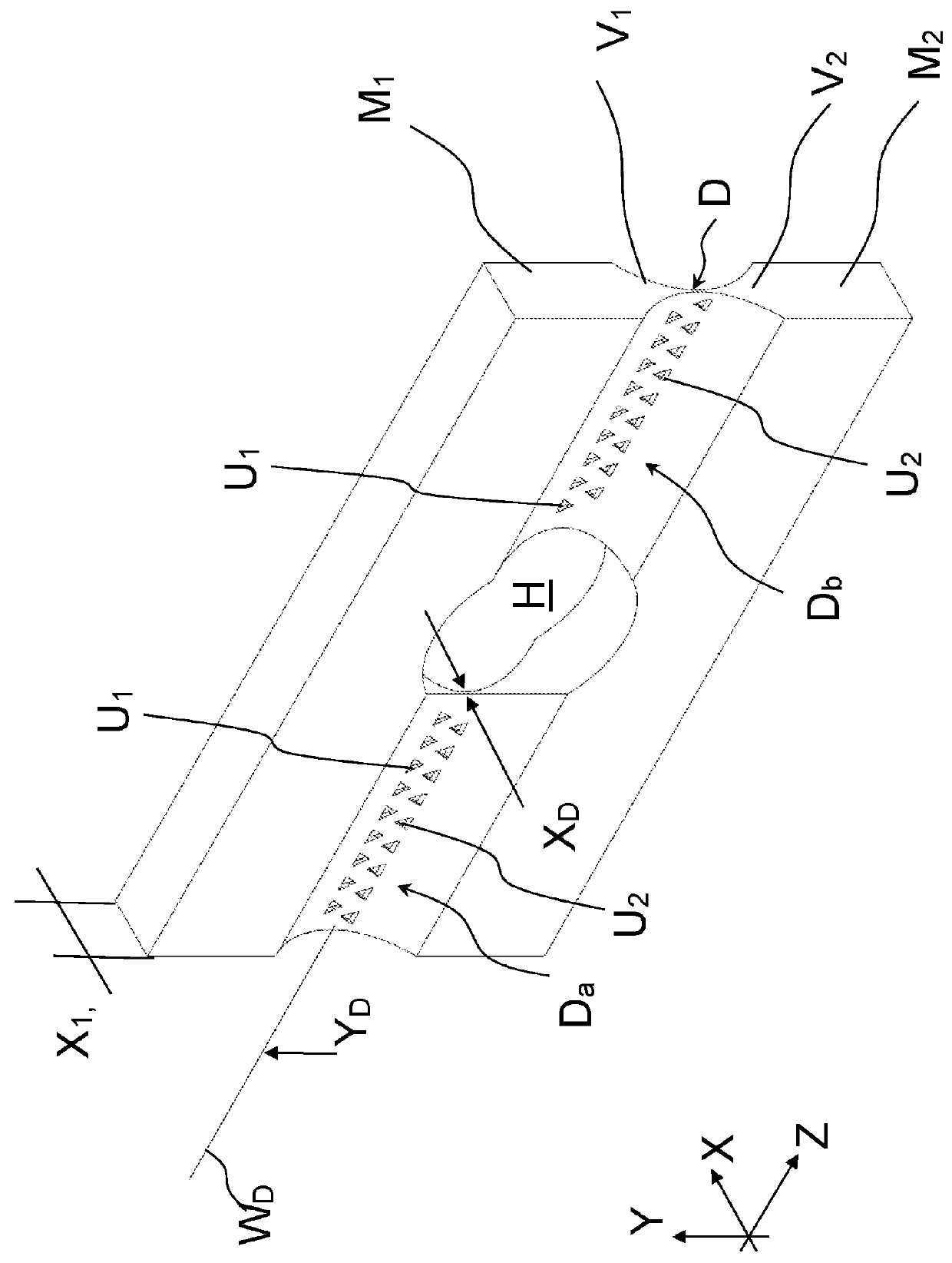
[0044]FIG. 1 shows a flexure hinge according to the invention in a simplified perspective view. The hinge comprises two material segments M1, M2, which are monolithically joined to each other via a thin spot D. The thin spot D is formed by two tapering sections V1, V2, which extend in a lengthwise direction Y toward each other as part of the material segments M1, M2, where the thickness measured perpendicular thereto in the X direction steadily decreases up to a minimal thickness XD, at which the actual thin spot D exists. It extends along a pivot axis WD in a width direction Z, which is perpendicular to the X and Y directions. The first material segment M1 can be pivoted with respect to the second material segment M2 about the thin spot D, where an idealized pivot axis WD runs in the Z direction at the lengthwise position YD of the thin spot D. An opening H made centrally in the thin spot D divides the thin spot into two segments Da and Db in the Z direction.

[0045]A plurality of re...


PUM

PropertyMeasurementUnit
thicknessaaaaaaaaaa
widthaaaaaaaaaa
strengthaaaaaaaaaa

Abstract

A flexure hinge with two material segments connected to each other via a material tapering to a thin spot which defines a pivot axis between the two material segments. The material segments are provided with recesses such that the strength existing in the thin spot with respect to normal stresses or bending stresses is kept largely constant within a distance from the thin spot.

Description

TECHNICAL FIELD OF THE INVENTION[0001]The invention concerns a flexure, or thin spot, hinge for movable connection of material segments.BACKGROUND OF THE INVENTION[0002]Hinges are often used in industry to connect components movably to each other. The hinges are intended to allow movements and transfers of force in certain directions, but prevent them in other directions. An example of this is a solid body or flexure hinge. In this case two material segments that are connected to each other monolithically are provided with a material tapering (a so-called “thin spot”) in order to enable movements about a pivot axis formed by the thin spot. Pivoting movements about axes perpendicular thereto and translatory relative movements of the two material segments, however, are prevented.[0003]Such flexure hinges are known in particular from modern weighing technology, which utilizes monolithic link arm mechanisms, so-called monoblocks. Through this, production costs are reduced and the precis...

Claims


Application Information

Patent Timeline
Patent Type & Authority Patents(United States)
IPC IPC(8): E05D1/00F16C11/12E05D1/02B23K26/384B23K26/06
CPCF16C11/12E05D1/02B23K26/384B23K26/0619G01G21/07G01G21/166G01G21/188G01G21/20G01G21/244
Inventor RUBEL, ANDREASBUR, CHRISTIAN
Owner WIPOTEC GMBH
Why Eureka
Try Eureka