Digital active array radar

a digital active array and radar technology, applied in the field of radar systems, can solve the problems that weight and power requirements may constrain the design of the radar system, and achieve the effects of reducing electromagnetic radiation, reducing radiation magnitude, and reducing radiation magnitud

Active Publication Date: 2018-05-15
HONEYWELL INT INC
View PDF20 Cites 14 Cited by
  • Summary
  • Abstract
  • Description
  • Claims
  • Application Information

AI Technical Summary

Benefits of technology

[0004]The disclosure describes radar systems and techniques for operating radar systems. The radar system described in this disclosure is a frequency modulated continuous wave (FMCW; transmits continuous waveforms rather than pulsed waveforms) radar system that includes a transmit array including a plurality of transmit antenna elements and a separate receive array that includes a plurality of receive antenna elements. In some examples, the transmit array may include a plurality of transmit antenna elements disposed such that the transmit antenna is wide in the horizontal dimension and short in the vertical dimension, or, alternatively, is tall in the vertical dimension and narrow in the horizontal dimension. This may produce a transmit beam that is elongated in a first illumination dimension compared to a second, substantially perpendicular illumination dimension. The radar system may electronically scan the transmit beam in the second illumination dimension to cover a large volume or surface in a reduced amount of time.
[0009]In some examples, the disclosure describes an FMCW radar array including a housing, a transmit array comprising a plurality of transmit antenna elements configured to output an FMCW transmit beam, a receive array comprising a plurality of receive antenna elements, and a slotted choke disposed between the transmit array and the receive array. The transmit array and the receive array may be mechanically coupled to the housing. In some examples, the slotted choke comprises a plurality of slots having dimensions selected to provide cancellation of electromagnetic radiation from the frequency modulated continuous wave transmit beam to reduce a magnitude of radiation from the transmit array to which the receive array is indirectly exposed.
[0010]In some examples, the disclosure describes a system including a plurality of frequency modulated continuous wave transmit beam (FMCW) radar arrays and a radome. Each of the FMCW radar arrays may include a housing, a transmit array comprising a plurality of transmit antenna elements configured to output an FMCW transmit beam, a receive array comprising a plurality of receive antenna elements, and a slotted choke disposed between the transmit array and the receive array. The transmit array and the receive array may be mechanically coupled to the housing. In some examples, the slotted choke comprises a plurality of slots having dimensions selected to provide cancellation of electromagnetic radiation from the frequency modulated continuous wave transmit beam to reduce a magnitude of radiation from the transmit array to which the receive array is indirectly exposed. Additionally, the slotted choke of each of the plurality of FMCW radar arrays may extend from between the transmit array and the receive array to an inner surface of the radome.
[0011]In some examples, the disclosure describes a method including mechanically coupling a transmit array comprising a plurality of transmit antenna elements configured to output an FMCW transmit beam to a housing of an FMCW radar array. The method also may include mechanically coupling a receive array comprising a plurality of receive antenna elements to the housing. In some examples, a slotted choke may be disposed between the transmit array and the receive array. The slotted choke may include a plurality of slots having dimensions selected to provide cancellation of electromagnetic radiation from the frequency modulated continuous wave transmit beam to reduce a magnitude of electromagnetic radiation from the transmit array to which the receive array is indirectly exposed.

Problems solved by technology

In smaller aircraft, such as some unmanned aerial vehicles (UAVs), weight and power requirements may constrain the design of the radar system.

Method used


Image

  • Digital active array radar
  • Digital active array radar
  • Digital active array radar

Examples


Embodiment Construction

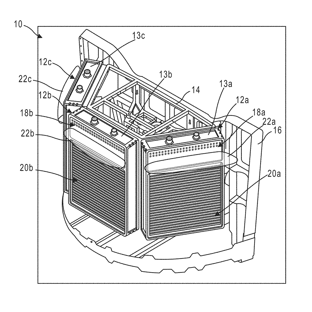
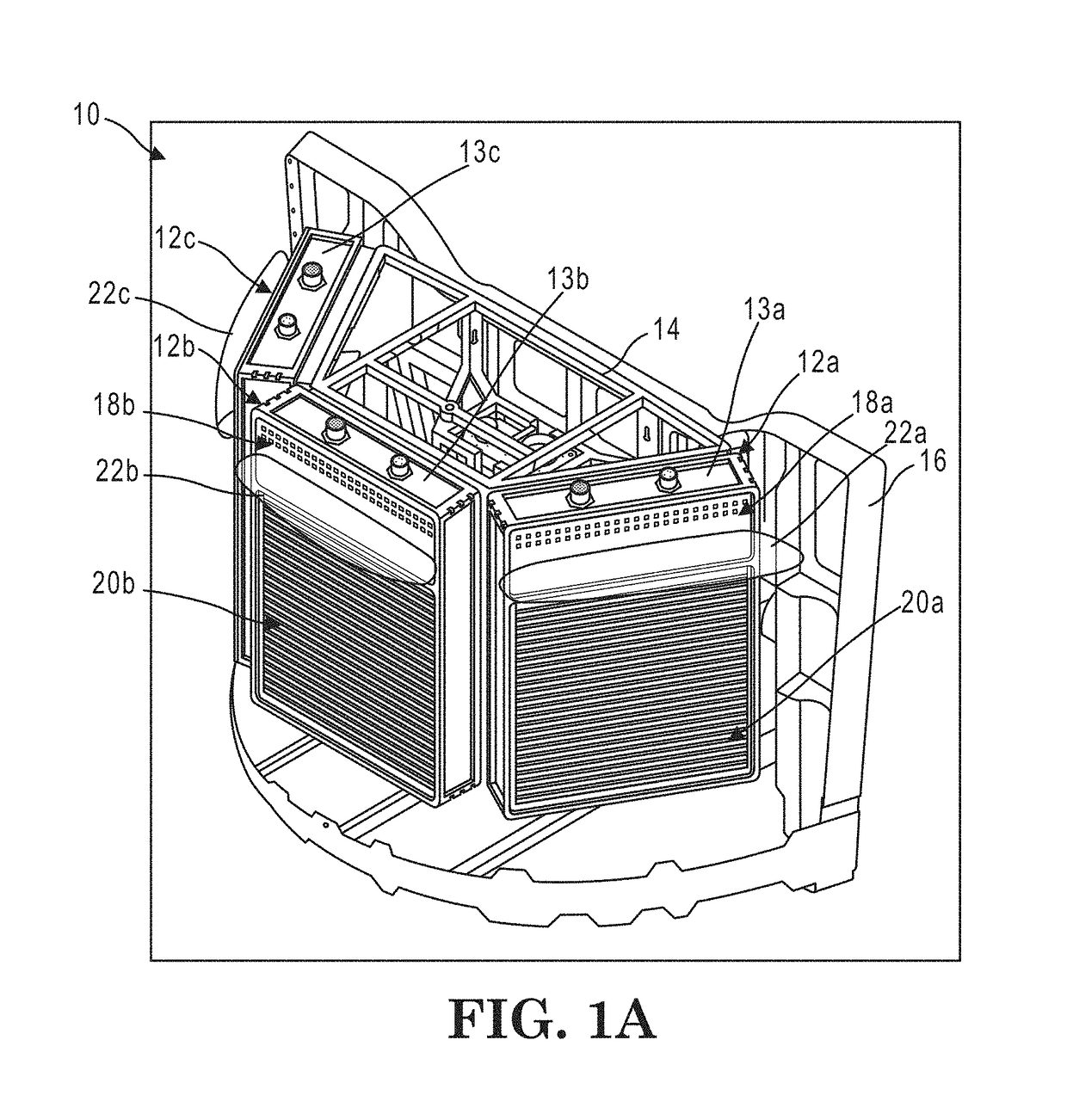
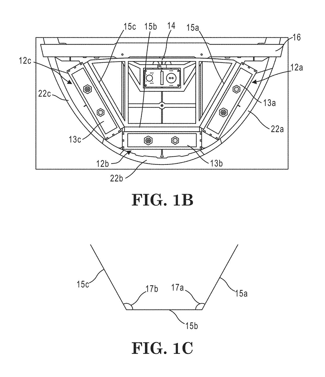
[0028]The disclosure describes radar systems and techniques for operating radar systems. Phased Array Surveillance Systems, particularly for small manned aircraft or UAVs, may advantageously use an efficient and low weight radar system for object sensing and avoidance or weather radar applications. The radar system described in this disclosure is a frequency modulated continuous wave (FMCW; transmits 100% of the time) radar system that includes a transmit array that includes a plurality of transmit elements and a separate receive array that includes a plurality of receive elements. In some examples, the radar system may include a plurality of transmit arrays and a plurality of receive arrays. For example, the radar system may include three transmit arrays and three receive arrays. By orienting the respective arrays at angles relative to each other, a greater range in azimuth, elevation, or both may be covered by the radar system. Additionally or alternatively, a plurality of transmi...


PUM


Abstract

In some examples, an FMCW radar array includes a housing, a transmit array comprising a plurality of transmit antenna elements configured to output an FMCW transmit beam, a receive array comprising a plurality of receive antenna elements, and a slotted choke disposed between the transmit array and the receive array. The transmit array and the receive array may be mechanically coupled to the housing. In some examples, the slotted choke comprises a plurality of slots having dimensions selected to provide cancellation of electromagnetic radiation from the frequency modulated continuous wave transmit beam to reduce a magnitude of radiation from the transmit array to which the receive array is indirectly exposed.

Description

[0001]This application claims the benefit of U.S. Provisional Patent Application No. 61 / 886,449, filed Oct. 3, 2013, entitled. “DIGITAL ACTIVE ARRAY RADAR,” the entire content of which is incorporated herein by reference.TECHNICAL FIELD[0002]The disclosure relates to radar systems.BACKGROUND[0003]Radar systems may be used by aircraft to detect weather, other aircraft in the surrounding airspace, and other objects in the surrounding airspace. In smaller aircraft, such as some unmanned aerial vehicles (UAVs), weight and power requirements may constrain the design of the radar system.SUMMARY[0004]The disclosure describes radar systems and techniques for operating radar systems. The radar system described in this disclosure is a frequency modulated continuous wave (FMCW; transmits continuous waveforms rather than pulsed waveforms) radar system that includes a transmit array including a plurality of transmit antenna elements and a separate receive array that includes a plurality of recei...

Claims


Application Information

Patent Timeline
Patent Type & Authority Patents(United States)
IPC IPC(8): H01Q21/20H01Q1/42H01Q13/20G01S7/35G01S13/02G01S7/02H01Q1/28
CPCH01Q21/20G01S7/35H01Q1/42H01Q13/20H01Q1/28G01S2007/027G01S2013/0245G01S13/34G01S13/4463H01Q1/525H01Q21/065G01S7/027
Inventor VACANTI, DAVID C.KOSTER, MICHAEL D.
Owner HONEYWELL INT INC
Why Eureka
Try Eureka