Electrical connector structure with improved ground member

a technology of ground member and electric connector, which is applied in the direction of coupling device connection, coupling protective earth/shielding arrangement, two-part coupling device, etc., can solve the problems of noise in the original transmitted high-frequency signal, and conventional data transmission methods cannot meet the requirements of high-speed information transmission, so as to improve the interference problem of high-frequency signals and effectively suppress high-frequency noise

Active Publication Date: 2018-05-15
SPEED TECH
View PDF4 Cites 49 Cited by
  • Summary
  • Abstract
  • Description
  • Claims
  • Application Information

AI Technical Summary

Benefits of technology

[0008]An embodiment of the present disclosure provides an electrical connector structure, and specially relate to an electrical connector structure, which is formed from a ground member, a fixing member, plural conductive terminals and plural bases. The present disclosure has a function for effectively suppressing high-frequency noise, and improves interference problems of high-frequency signals.

Problems solved by technology

Due to the extensive development of information technology and dramatically increasing various files and video streaming information, conventional data transmission methods cannot meet requirements of high-speed information transmission.
Because of the reduced distances, when high-speed signals are transmitted in the terminals, cross talks are likely to occur in adjacent terminals, thus resulting in noises in the originally transmitted high-frequency signals.

Method used


Image

  • Electrical connector structure with improved ground member
  • Electrical connector structure with improved ground member
  • Electrical connector structure with improved ground member

Examples


first embodiment

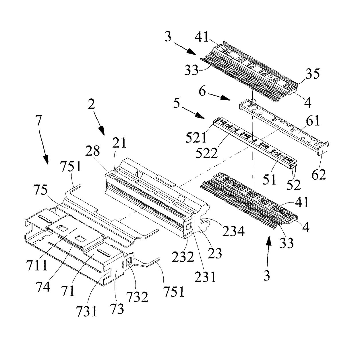
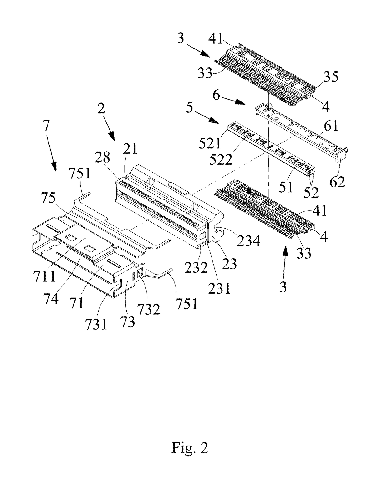
[0039]In the present disclosure, referring to FIG. 5 and FIG. 6, each of the contact arms 521 on the surfaces of the ground plates 52 of the ground member 5 is a rib structure 521a which is formed by punching the surface of each ground plate 52. The rib structure 521a is a rectangular thin plate protruding from each of the ground plates 52, and each rib structure 521a has a contact section (not shown). The contact sections are parallel to the ground plates 52, and the two ends of the each contact section extend to connect the surface of the ground plate 52. The rib structures 521a are parallel to each other and have no elasticity, and the rib structures 521a are in contact with and electrically connected to the corresponding ground terminals 32 through the second openings 412 of the bases 4. The contact section of the rib structures 521a has a flat contact surface which is in contact with the ground terminals 32, and the contact surface is larger than the contact surface of the conv...

third embodiment

[0041]In the present disclosure, referring to FIG. 9 and FIG. 10, each contact arm 521 of the ground plates 52 surfaces of the ground member 5 is formed from a second elastic arm 521c. The second elastic arms 521c are formed by punching the ground member 5. Each second elastic arm 521c extends from the connecting portion 51 of ground member 5 to ground plate 52 of ground member 5, and the second elastic arms 521c protrude from the surface of the ground plate 52. The ends of second elastic arm 521c extend along a direction toward to the surfaces of ground plates 52, and the second elastic arms 521c are in contact with and electrically connected to the connecting portion 51. A width of portions of the second elastic arms 521c adjacent to the connecting portion 51 is wider than the end width of the second elastic arms 521c. The width of each second elastic arm 521c from the connecting portion 51 to the end of ground terminal 32 is gradually decreased, and the end of each second elastic...

fourth embodiment

[0042]In the present disclosure, the second openings 412 of the bases 4 respectively expose the ground terminals 32, and the second openings 412 are not limited to be designed on the facing surfaces of the bases 4, and the second openings 412 can be designed on the opposite and exterior surfaces of the bases 4. The ground plates 52 of the ground members 5 are disposed independently, and aren't connected to each other. The surfaces of the ground plate 52 have the protruding elastic arms or the ribs, and the ground plates 52 are fixed in the exterior surfaces of the bases 4, the facing interior surfaces, or both the exterior surfaces and interior surfaces of the bases 4. The elastic arms or the ribs are connected to the ground terminals 32 of the bases 4 by the second openings 412. In order to achieve a better earthing effect, the ground plates 52 can be fixed into the surfaces of the bases 4 by any one of hot pressing, engaging, clamping and embedding

[0043]In some embodiments of the ...


PUM


Abstract

A electrical connector structure includes ground terminals formed in two rows, which are fixed into two bases respectively, in which each of the ground terminals includes a contact portion, a soldering portion and a main body is connected to the contact portion and the soldering portion, and each main body is fixed into the bases, and each soldering portion extends out of the bases; and a ground member including two ground plates, in which the ground plates covering surfaces of the bases, respectively, and a surface of each ground plate has a plurality of contact arms protruding, the contact arms are electrically contacted to the ground terminals, respectively, in which two ends of each contact arm contact the ground plates, respectively.

Description

RELATED APPLICATIONS[0001]This application claims priority to Taiwan Application Serial Number 106204894, filed Apr. 6, 2017, which is herein incorporated by reference.BACKGROUNDTechnical Field[0002]The present disclosure relates to an electrical connector structure. More particularly, the present disclosure relates to a technology for shielding an electromagnetic signal.Description of Related Art[0003]Due to the extensive development of information technology and dramatically increasing various files and video streaming information, conventional data transmission methods cannot meet requirements of high-speed information transmission. For a serial technology required for high-speed information access, serial attached SCSI (SAS) can be used to overcome the bottleneck of a conventional parallel technology, and provides a faster data transmission function. The SAS can support and is compatible with serial advanced technology attachment (SATA), and thus has advantages of broad applicab...

Claims


Application Information

Patent Timeline
Patent Type & Authority Patents(United States)
IPC IPC(8): H01R13/648H01R13/6585H01R24/60H01R13/6586
CPCH01R13/6585H01R24/60H01R13/6586H01R12/721
Inventor HUANG, KUO-HUAHSIEH, I-TING
Owner SPEED TECH
Why Eureka
Try Eureka