

Tibial cutting block
a technology of tibial and tibial bones, which is applied in the field of surgical devices, can solve the problems of comparatively complex, high maintenance costs, and high risk of failure of each setting or adjustment, and achieve the effects of precise tibial cutting, small size and simple structur
- Summary
- Abstract
- Description
- Claims
- Application Information
AI Technical Summary
Benefits of technology
Problems solved by technology
Method used
Image

Examples
Embodiment Construction
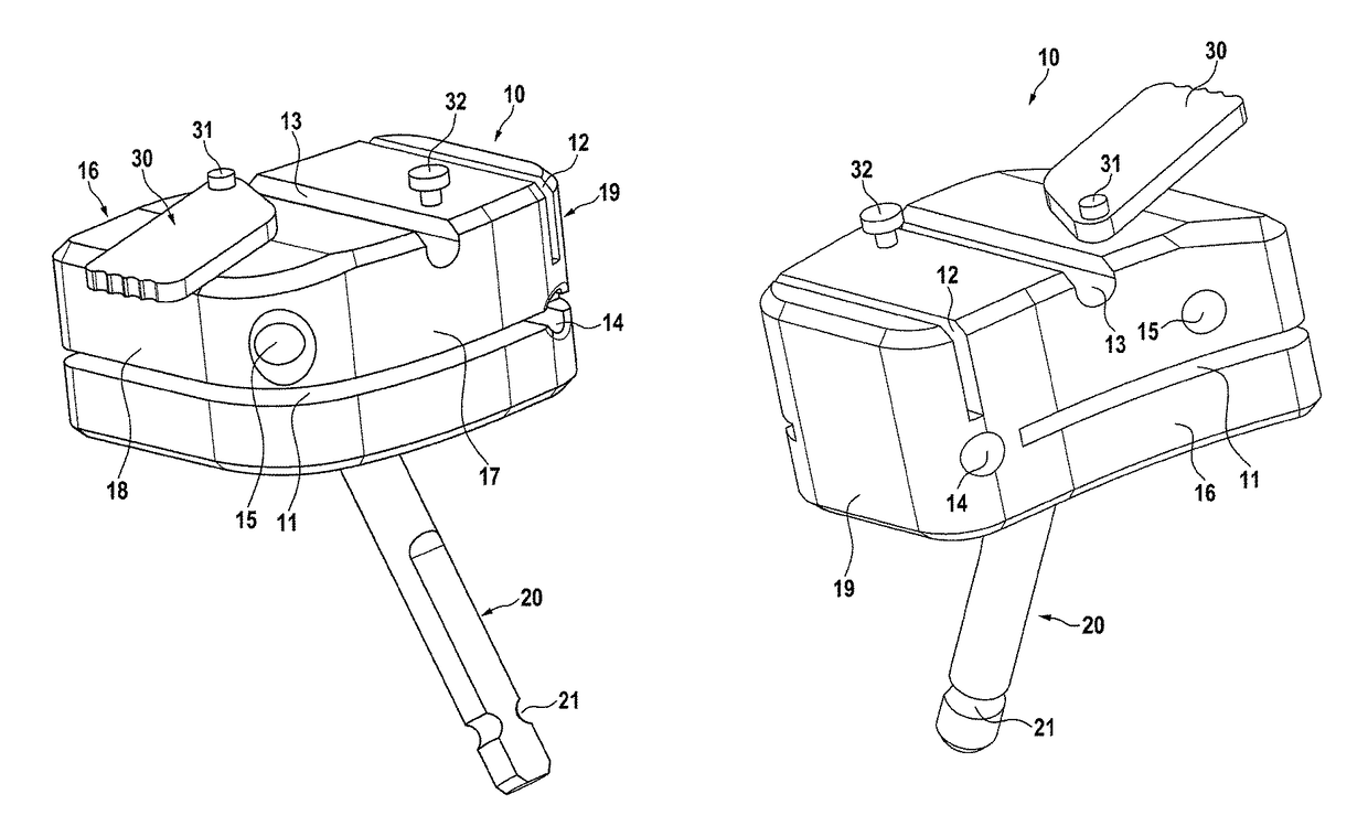
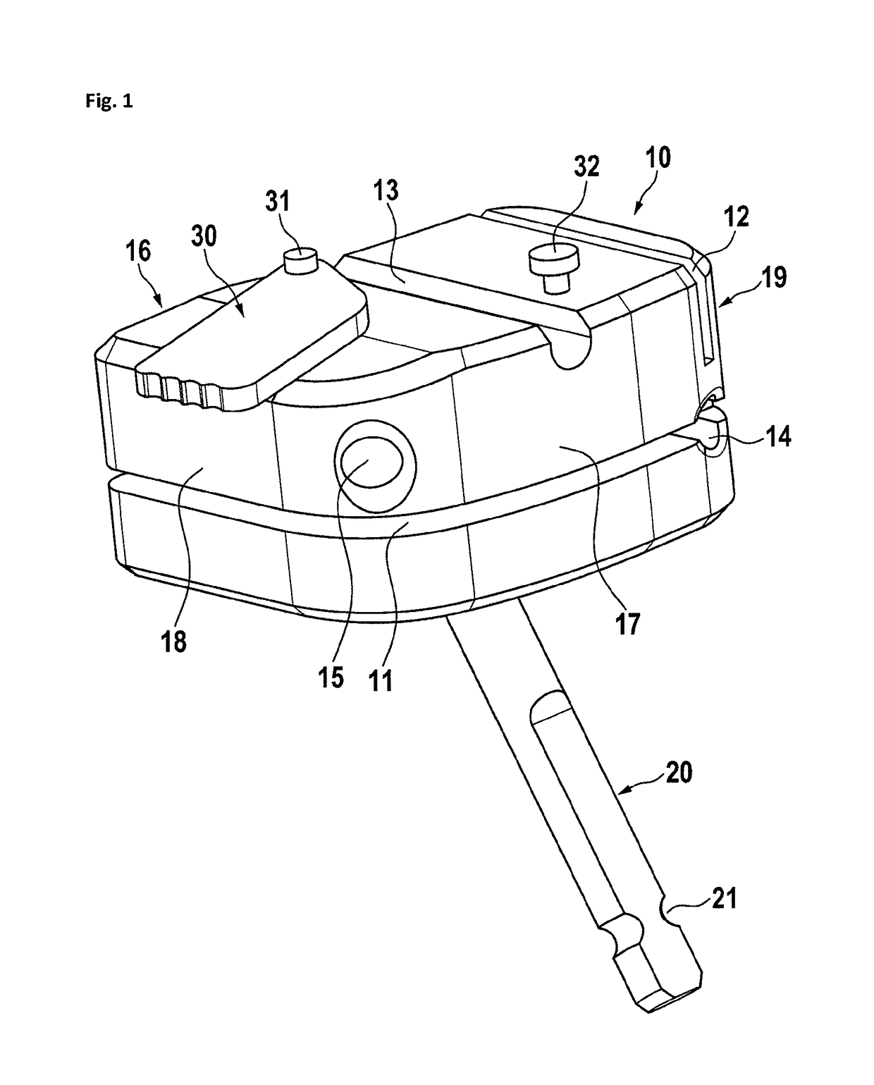
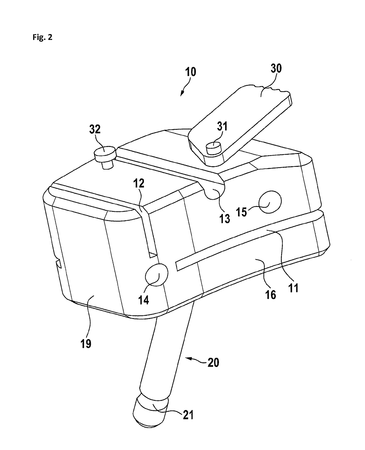
[0038]In FIG. 1, a preferred embodiment of a tibia cutting block is shown. The tibia cutting block 10 has a tibia attachment side 16 and opposed thereto a front side 17. Furthermore, there is a left side 19 and a right side 18. In this embodiment, the right side is oriented to the cruciate ligament while the left side is oriented medial or lateral. Therefore, this cutting block may be used lateral at the right tibia or medial at the left tibia. A cutting block for use lateral at the left tibia or medial at the right tibia, the sides left and right as related to the cutting block are reversed. On the front side, the cutting block has a first anchoring pin hole 14 and a second anchoring pin hole 15, both define basically anterior-posterior oriented channels through the cutting block and allow the insertion of anchoring pins for holding the cutting block to the tibia. Preferably, the channels through the anchoring pin holes are under an angle between 10 and 30 degrees, most preferably ...
PUM
 Abstract
Description
Claims
Application Information