Pilot operated parallel valve

a parallel valve and pilot valve technology, which is applied in the direction of fluid pressure control, ratio control, instruments, etc., can solve the problems of too large valve error percentage for the full scale of the valve, and too low flow imprecision to the application, so as to achieve low flow precision, high flow capability, and insensitive to position or vibration

Active Publication Date: 2018-05-22
KELLY EDMUND F
View PDF3 Cites 3 Cited by
  • Summary
  • Abstract
  • Description
  • Claims
  • Application Information

AI Technical Summary

Benefits of technology

[0006]It is an object of the present invention to provide a mechanism and method which incorporates valves mounted in parallel for controlling a broad range of pneumatic flow rates. It is envisioned that a small, fast, proportionally acting electropneumatic valve pilot operates a larger mechanical valve to obtain a desired low flow precision control white it also allows for high flow capability.
[0007]It is an object to provide a mechanism that is small, lightweight, and insensitive to position or vibration; it can readily mount in a process line to be controlled at its work point.
[0008]It is an object that the present mechanism can be remotely or locally operated by a process controller or another electrical device. There is also both internal and external feedback whereby accurate repeated operation of the mechanism is ensured.
[0009]The present invention establishes a unique electropneumatic proportional flow control device that allows for improved control. The device configuration incorporates two internal valves in parallel a first electronically controlled, miniature proportional valve manipulated in parallel with a second and larger pilot-operated valve. The miniature valve allows for precision control of the low-end of the full scale output; the larger mechanical valve allows for the high-end of the full scale output. These valves are encompassed within a valve assembly comprising a valve manifold, a pilot-operated diaphragm, electronic control circuitry, and a flow restrictor. The device can obtain a flow output turndown ratio of 100,000:1.

Problems solved by technology

A problem is that these units generally do not offer precision flow at lower rates, the valve percentage of error for the full scale of the valve may be too great; and, the low flow imprecision can be too problematic to the application.

Method used


Image

  • Pilot operated parallel valve
  • Pilot operated parallel valve

Examples


Embodiment Construction

[0012]The best mode for carrying out the invention is presented in terms of its preferred embodiment, herein depicted with the Figures:

1. Detailed Description of the Figures

[0013]To promote an understanding of the principles of the present invention, the embodiment is hereafter explained with reference to respective drawings as well as to specific language to describe the same.

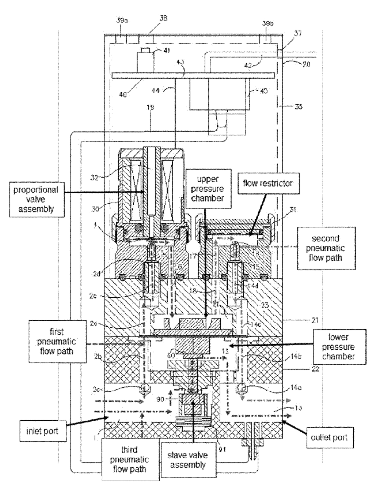
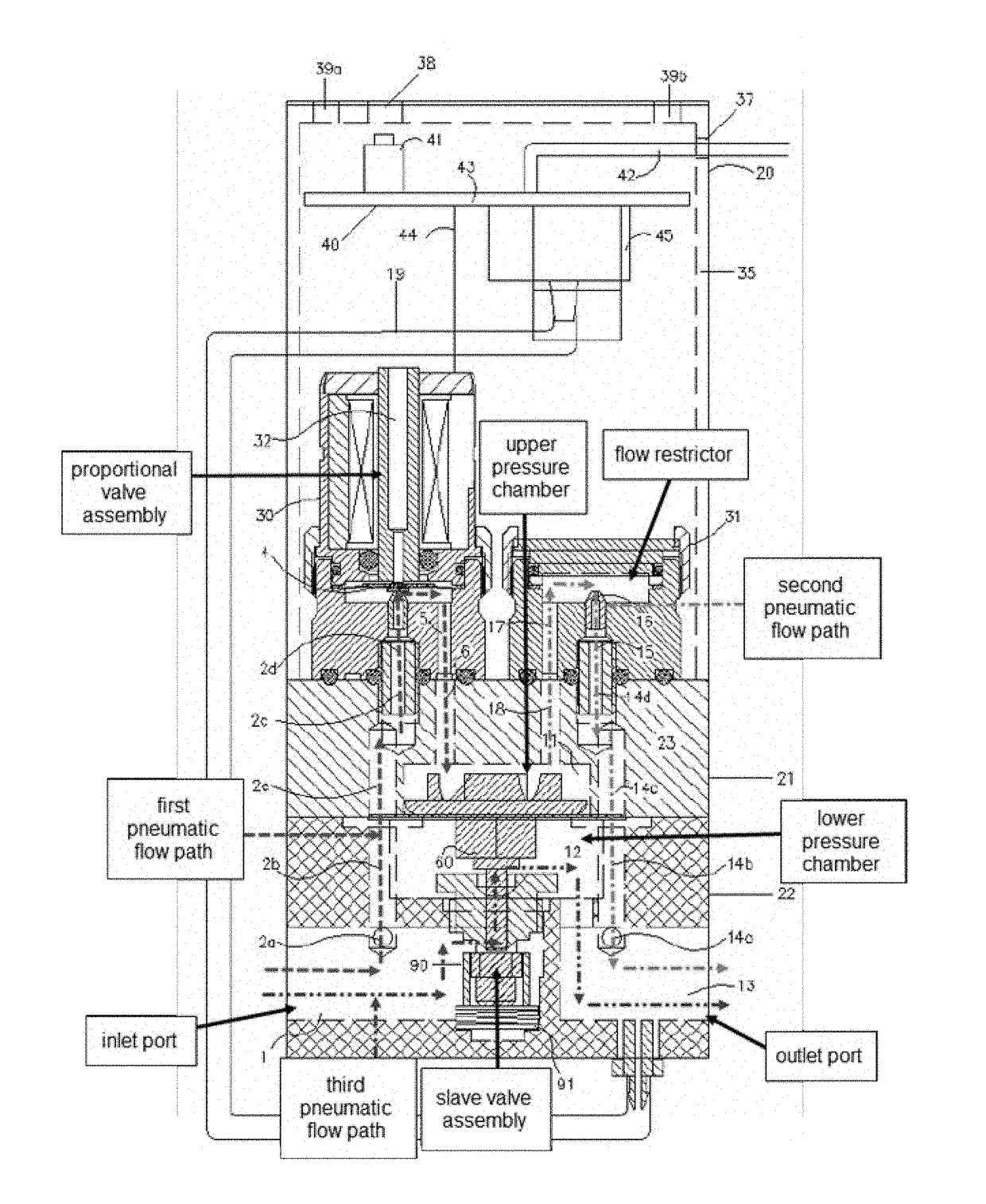
[0014]FIG. 1 shows a mechanical construction to which the primary embodiment of the invention is applied. As shown in FIG. 1, an electropneumatic controller 20 is operationally attached to pilot operated valve 22. Pilot operated valve 22 operates in response to an incoming pneumatic pressure at pressure inlet port 1, as well as to electronic signals received by electronic control circuitry 40, to regulate a corresponding volumetric chamber pressure contained by lower pressure chamber 12, which in turn outputs pneumatically controlled flow output via outlet port 13. Thus, pilot operated valve 22 acts as a press...


PUM


Abstract

An electropneumatic proportional flow control device improves flow control because it incorporates two internal valves in parallel: a first electronically controlled, miniature proportional valve manipulated in parallel with a second and larger pilot -operated valve. The miniature valve allows for precision control of the low-end of the full scale output; the larger mechanical valve allows for the high-end of the full scale output. These valves are encompassed within a valve assembly comprising a valve manifold, a pilot-operated diaphragm, electronic control circuitry, and a flow restrictor.

Description

FIELD OF THE INVENTION[0001]The present invention relates generally to a device for electropneumatic control of pneumatically operated valves and, more specifically to a valve having two bodies that operate in parallel: a small valve pilot operates an overlapping large valve body.BACKGROUND OF THE INVENTION[0002]Numerous types of proportional pneumatic flow control valves are presently available which accurately control flow over a wide range of flow control applications. These single valves are typically calibrated to a specific range of flow rates; the accuracy of these valves is dependent upon the total range of capable flow, which is otherwise known as the “Full Scale” of the valve. A problem is that these units generally do not offer precision flow at lower rates, the valve percentage of error for the full scale of the valve may be too great; and, the low flow imprecision can be too problematic to the application.[0003]Heretofore, there is known means to proportionally control ...

Claims


Application Information

Patent Timeline
Patent Type & Authority Patents(United States)
IPC IPC(8): G05D11/13
CPCG05D11/132G05D16/2022G05D16/2095
Inventor KELLY, EDMUND F.
Owner KELLY EDMUND F
Why Eureka
Try Eureka