
Method and system for multipath reduction for wireless synchronizing and/or locating

a wireless synchronization and multi-path technology, applied in wave based measurement systems, measurement devices, instruments, etc., can solve the problems of inability to install, error in the synchronization of location receivers, and high installation costs of wired connections, so as to maximize the capacity of location tags in the system, the air time used for location anchor synchronization is minimized and the effect of minimizing the tim

Active Publication Date: 2018-05-29
NANOTRON GES FUR MIKROTECHN
View PDF13 Cites 3 Cited by
  • Summary
  • Abstract
  • Description
  • Claims
  • Application Information

AI Technical Summary

Benefits of technology

The present invention introduces a real-time locating method and system without the need for reference tags and synchronization without additional measurements. It eliminates the effect of multipath error and maximizes the capacity of location tags in the system. The method allows for precise distance and position determination, as well as detailed information on the multipath situation. It can be applied to small, large, and very large systems with in principle unlimited numbers of location anchors distributed over a wide spatial area.

Problems solved by technology

Obviously, however, a wired connection is expensive to install and in some cases may even be impossible to install.
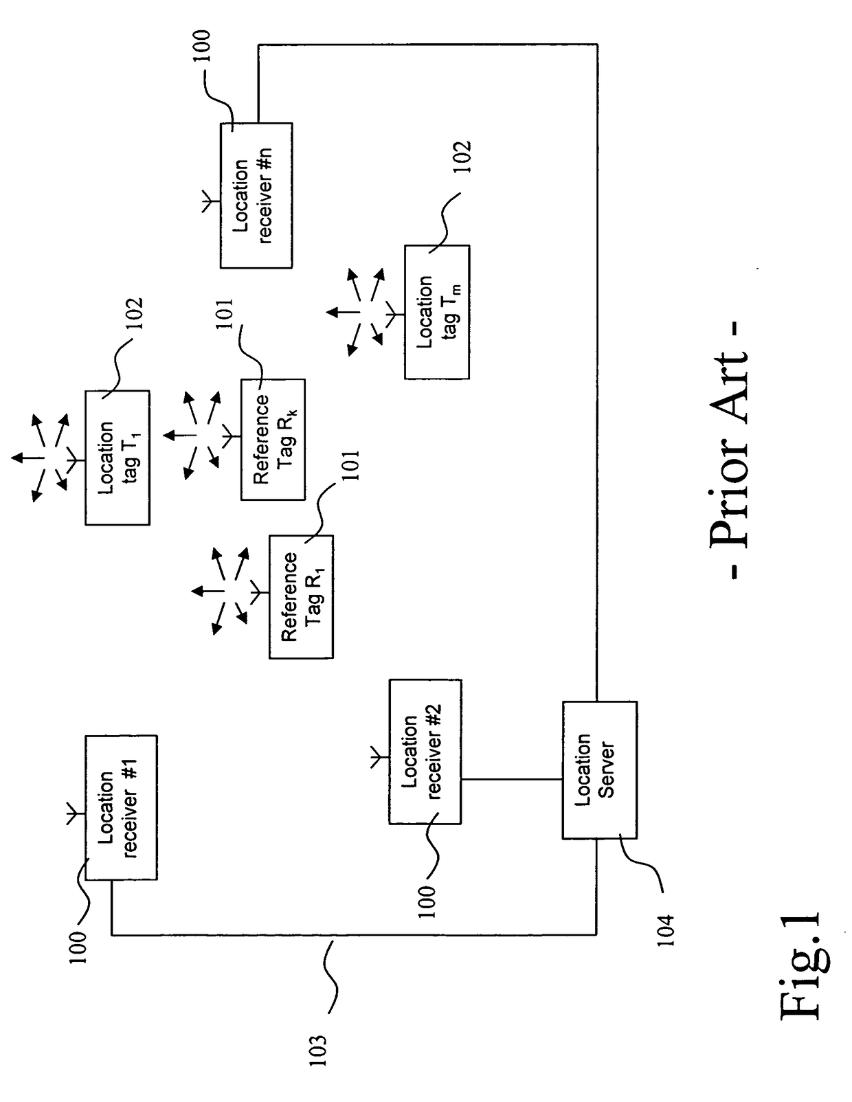
This multipath propagation causes an error in the synchronization of the location receivers 100.
Thus, the synchronization between location receivers 100 and the subsequent calculations of TDOAs and locations of location tags may be highly inaccurate in a multipath environment.
A drawback of the approach disclosed in US 2008 / 0095131 A1 lies in the fact that the accuracy of the two-way ranging will strongly depend on the accuracy of the time bases of the location receivers involved.
Furthermore, this approach puts additional hardware complexity and additional processing load on the location receivers by requiring the handling of the two-way ranging process, which consumes additional airtime and energy.

Method used


Image

  • Method and system for multipath reduction for wireless synchronizing and/or locating
  • Method and system for multipath reduction for wireless synchronizing and/or locating
  • Method and system for multipath reduction for wireless synchronizing and/or locating

Examples


Embodiment Construction

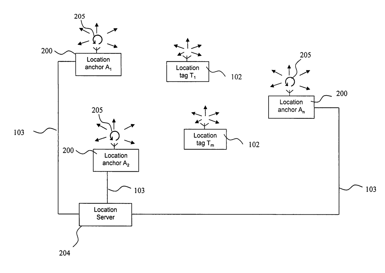
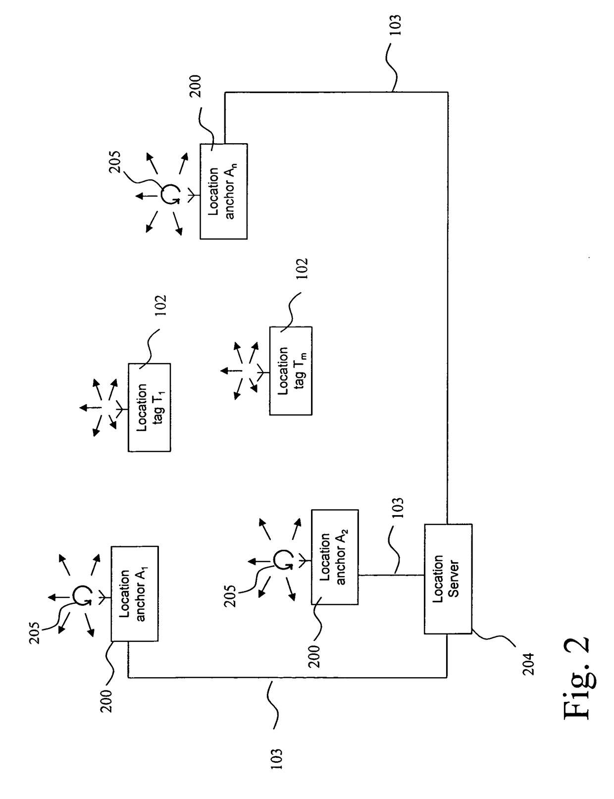
[0121]A first embodiment of the invention is depicted in FIG. 2. For the purpose of clarity, those location receivers, which have wireless receivers and which are located at known positions will be called location anchors in the following and share the reference label 200. The location anchors 200 are each connected with at least one location server 204 through some communication channel 103, which may be wired or wireless, the latter including, but not being limited to a radio communication, infrared or acoustic communication channel.

[0122]The location anchors 200 are capable of wirelessly transmitting signals. Each or at least some of the location anchors 200 are also capable of receiving wirelessly transmitted signals or messages from other location anchors 200, and they are capable of receiving wirelessly transmitted signals or messages from location tags 102, the position of which is initially unknown and which are thus to be located.

[0123]Furthermore the location anchors 200 a...


PUM


Abstract

A method for determining an instantaneous phase difference between time bases of at least two location anchors for a desired point in time (t), each of the location anchors having transmitting and receiving access to a joint broadcast transmission medium and a respective time base for measuring time, wherein a first of the location anchors broadcasts a first broadcast message at least twice; the first location anchor and at least a second of the location anchors receive the first broadcast messages; the second location anchor broadcasting a second broadcast message at least twice; and the second location anchor and at least the first location anchor receive the second broadcast messages. The location server calculates the instantaneous phase difference from a determined first and second clock model functions and from a time elapsed between a reference point in time and the desired point in time t.

Description

CROSS REFERENCE TO RELATED APPLICATIONS[0001]This application claims priority under 35 USC § 119(e) to European Patent Application No. 11 166 284.7 filed on May 16, 2011 and European Patent Application No. 11 181 681.5 filed on Sep. 16, 2011, which applications are hereby incorporated by reference.FIELD OF THE INVENTION[0002]The present invention relates to the field of wireless synchronization, which can be used for instance in Real Time Locating Systems (RTLS) based on Time Difference Of Arrival (TDOA).BACKGROUND OF THE INVENTION[0003]In Real Time Locating Systems, which utilize a Time Difference Of Arrival of messages transmitted by location tags and received by location receivers, time base synchronization between location receivers is a key task.[0004]In the context of the present specification, synchronization is to be understood as a determination of a synchronization correction value, which describes the difference between the time assessed in accordance with the different t...

Claims


Application Information

Patent Timeline
Patent Type & Authority Patents(United States)
IPC IPC(8): G01S5/06G01S5/00G01S5/02
CPCG01S5/06G01S5/021G01S5/0081G01S5/02216
Inventor HACH, RAINERROMMEL, ALBRECHT
Owner NANOTRON GES FUR MIKROTECHN
Learn More