Fuel assembly for a nuclear boiling water reactor

a fuel assembly and boiling water technology, applied in reactor fuel elements, nuclear elements, greenhouse gas reduction, etc., can solve the problems of increasing the corrosion and erosion of the spacer material, harming the integrity of the spacer, and weakening the mechanical strength of the spacer grid in the central region, so as to improve the cold shut-down margin, the effect of low reactivity and high reactivity

Active Publication Date: 2018-05-29
WESTINGHOUSE ELECTRIC SWEDEN
View PDF7 Cites 1 Cited by
  • Summary
  • Abstract
  • Description
  • Claims
  • Application Information

AI Technical Summary

Benefits of technology

[0009]An object of the present invention is to provide a fuel assembly for a nuclear boiling water reactor with an improved cold shut-down margin, i.e. the reactivity should be sufficiently low when the nuclear reactor is shut down (cold condition). A further object is to provide such a fuel assembly which has a high reactivity when the nuclear reactor is in operation (hot condition). A further object is to provide such a fuel assembly which has a fission power distributed evenly over the cross-section of the fuel assembly. A further object is to provide such a fuel assembly which has a reduced pressure drop in the upper two-phase flow region, in order to improve thermal-hydraulic stability. Another object is to provide such a fuel assembly in which the risk to cause damage to spacer grids positioned at higher levels in the fuel assembly (above shorter fuel rods) is low. Still another object is to provide such a fuel assembly which has an advantageous nuclear performance.

Problems solved by technology

A too high flow velocity in this region could increase the corrosion and erosion of the spacer material positioned at higher levels in the fuel assembly.
Loss of spacer material by erosion can harm the spacer integrity.
However, this weakens the mechanical strength of the spacer grids in the central region when exposed to external loads, e.g., during transport or in an earthquake event.

Method used


Image

  • Fuel assembly for a nuclear boiling water reactor
  • Fuel assembly for a nuclear boiling water reactor
  • Fuel assembly for a nuclear boiling water reactor

Examples


Embodiment Construction

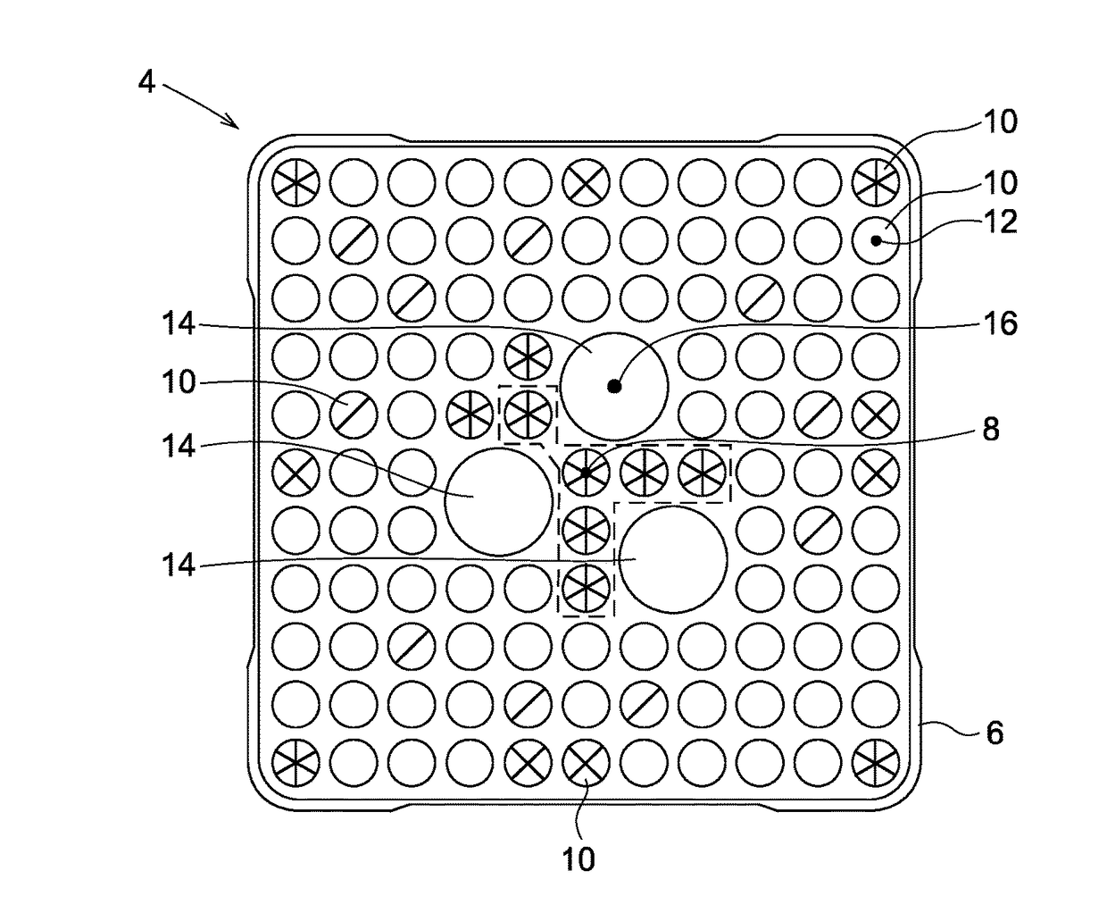
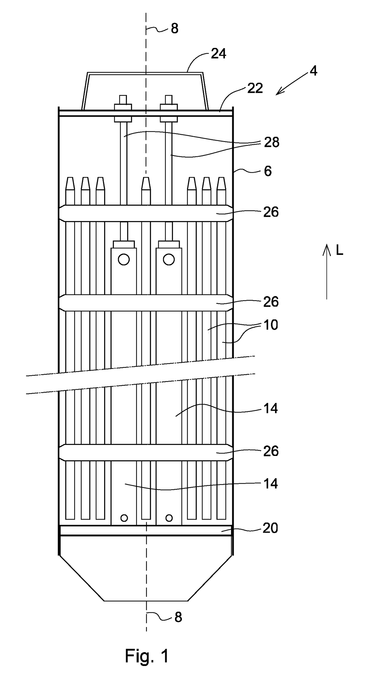
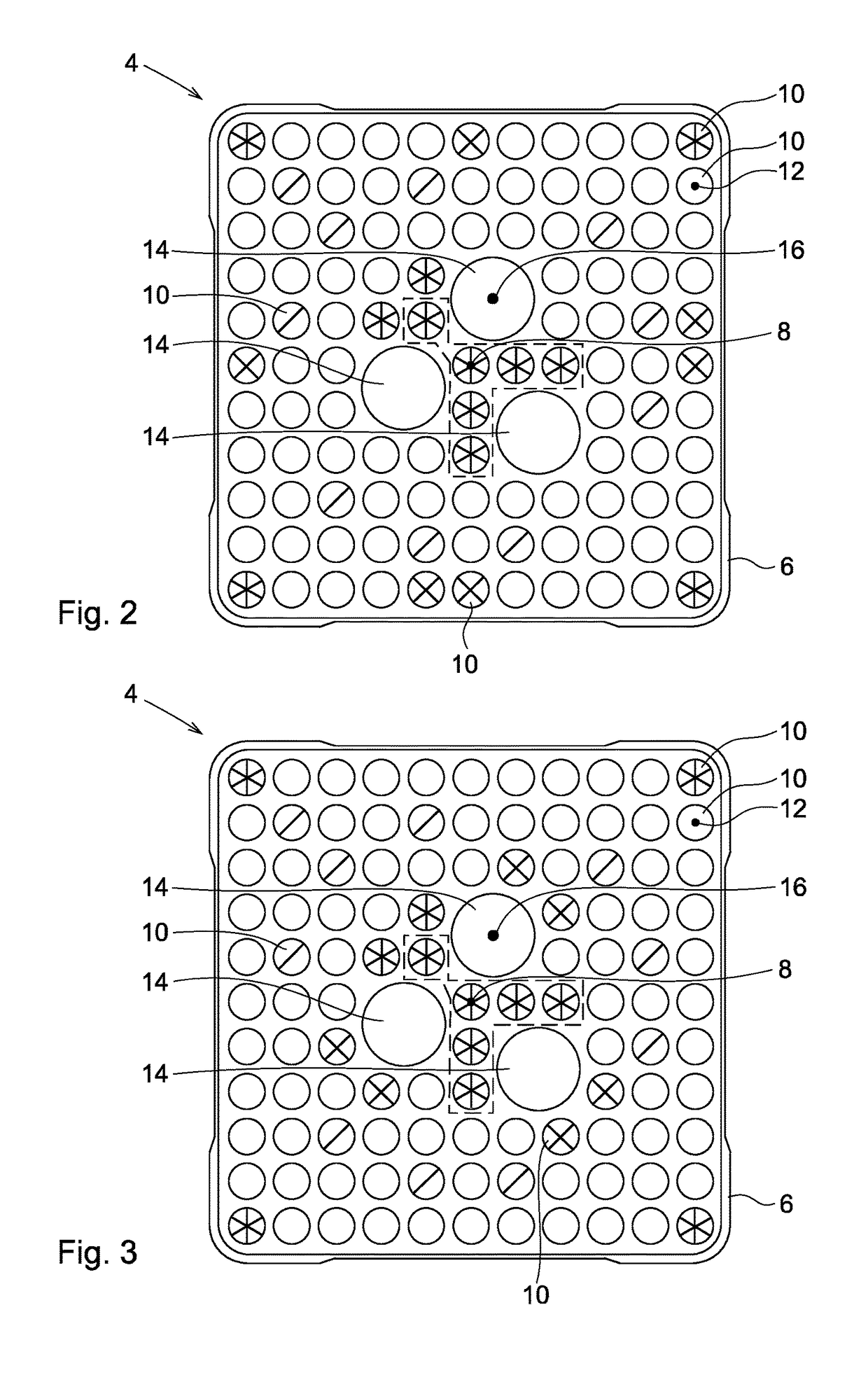
[0056]A first embodiment of the invention will now be described with reference to FIG. 1 and FIG. 2.

[0057]FIG. 1 shows schematically a side view of a fuel assembly 4 according to an embodiment of the invention. The fuel assembly 4 comprises a number of fuel rods 10 and water channels 14. A lower tie plate 20 is arranged below the fuel rods 10. A lower end of the water channels 14 is attached to the tie plate 20. Above the fuel rods 10 an upper lifting device 22 is arranged. The upper lifting device 22 has a handle 24 for gripping and lifting a bundle of fuel rods 10.

[0058]The fuel rods 10 are held by a plurality of spacer grids 26. It should be noted that FIG. 1 schematically shows only an upper and lower part of the fuel assembly 4. According to an embodiment, the fuel assembly 4 comprises ten spacer grids 26. The fuel assembly 4 also comprises attachment rods 28, which at a lower end are attached to the upper part of the water channels 14 and which at an upper end are attached to ...


PUM


Abstract

A fuel assembly for a nuclear power boiling water reactor including a fuel channel defining a central fuel channel axis, fuel rods, each having a central fuel rod axis, at least 3 water channels for non-boiling water, each water channel having a central water channel axis and each water channel having a larger cross-sectional area than the cross-sectional area of (the average) fuel rod. The fuel rods include a first group of full length fuel rods and a second group of shorter fuel rods. The fuel assembly comprises 3 or 4 fuel rods which belong to said second group and which are positioned such that the central fuel rod axis of each of these 3 or 4 fuel rods is closer to the central fuel channel axis than any of the water channel axes of the water channels.

Description

FIELD[0001]The present invention concerns a fuel assembly for a nuclear power boiling water reactor.BACKGROUND[0002]In a fuel assembly for a nuclear boiling water reactor, there are a number of fuel rods, which comprise a nuclear fuel material. When the fuel assembly is in operation in a nuclear reactor, a cooling medium, usually water, flows up through the fuel assembly. This water fulfills several functions. It functions as a cooling medium for cooling the fuel rods such that they will not be overheated. The water also serves as a neutron moderator, i.e. the water slows down the neutrons to a lower speed. Thereby, the reactivity of the reactor is increased.[0003]Since the water flows upwards through the fuel assembly, in the upper part of the fuel assembly, the water has been heated to a larger extent. This has as a consequence that the portion of steam is larger in the upper part of the fuel assembly than in the lower part. Since steam has a relatively low density, the steam in t...

Claims


Application Information

Patent Timeline
Patent Type & Authority Patents(United States)
IPC IPC(8): G21C3/328G21C3/322
CPCG21C3/328G21C3/322G21C2003/3225G21C3/3225Y02E30/30
Inventor AUREN, JONASBERGMANN, UFFE
Owner WESTINGHOUSE ELECTRIC SWEDEN
Why Eureka
Try Eureka