Spatial zoom mode for accumulative trapped ion mobility spectrometry

a technology of accumulative trapped ions and spatial zoom, which is applied in the direction of mass spectrometers, instruments, stability-of-path spectrometers, etc., can solve the problems of high-mass ions being piled out of the tunnel, ion loss, and inability to achieve temporal zoom mode with drift tubes, so as to reduce the effect of space charge effects

Active Publication Date: 2018-05-29
BRUKER DALTONICS INC
View PDF7 Cites 3 Cited by
  • Summary
  • Abstract
  • Description
  • Claims
  • Application Information

AI Technical Summary

Benefits of technology

[0014]In contrast to the “temporal zoom” described in U.S. Pat. No. 8,766,176 B2, the zoom according to this invention will be called “spatial zoom” because the zoom spreads the ions of the mobility range of interest over almost the full space of the ion mobility scanning tunnel. If additionally an accumulation tunnel is used, the ions of the mobility range of interest are likewise spread over almost the full space of this tunnel. The spatial zoom advantageously can collect considerably more ions of interest than the temporal zoom without severe losses by space charge effects, and more ions can be detected in the mass-mobility map.
[0021]An additional voltage at or near the entrance of the scan unit can further be adjusted such that the ions of the selected range of mobilities spread over the full length of the scan unit to reduce space charge effects. The inflow of ions into the accumulation cell is preferably stopped during the transfer step, for example by adjusting a DC voltage at or near or upstream of the accumulation unit. The steps (a) to (c) can be repeated with different ranges of mobilities by adjusting the voltages of the accumulation and / or scan unit.

Problems solved by technology

Such a temporal zoom mode is not achievable with drift tubes or any other type of mobility spectrometers.
High mass ions are highly endangered to be piled out of the tunnel by space charge forces because they are only weakly bound inside the tunnel by the quadrupolar RF field.
In both the ion accumulation tunnel and the ion mobility scanning tunnel, the ions are gathered on an electric field ramps, separating the ions according to their mobility and diminishing the deteriorating effect of space charge on the ion collection causing ion losses.

Method used


Image

  • Spatial zoom mode for accumulative trapped ion mobility spectrometry
  • Spatial zoom mode for accumulative trapped ion mobility spectrometry
  • Spatial zoom mode for accumulative trapped ion mobility spectrometry

Examples


Embodiment Construction

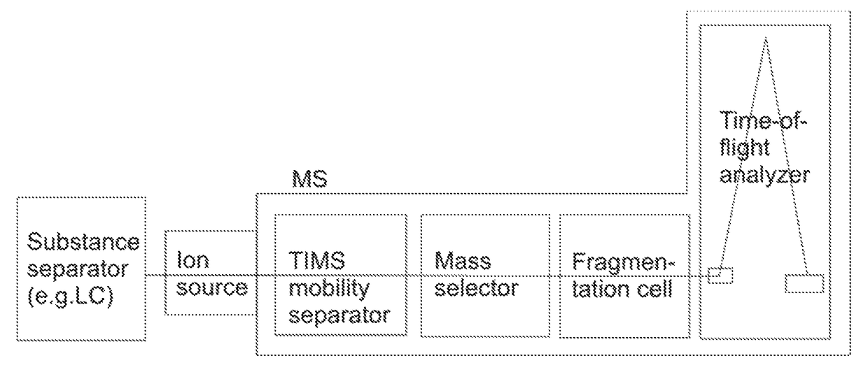
[0037]The invention is based upon the ion mobility spectrometer (“TIMS”) presented in U.S. Pat. No. 7,838,826 B1, and particularly to the TIMS device with parallel accumulation as described in U.S. Ser. No. 14 / 614,456 and equipped with ion accumulation tunnel and ion mobility scanning tunnel.

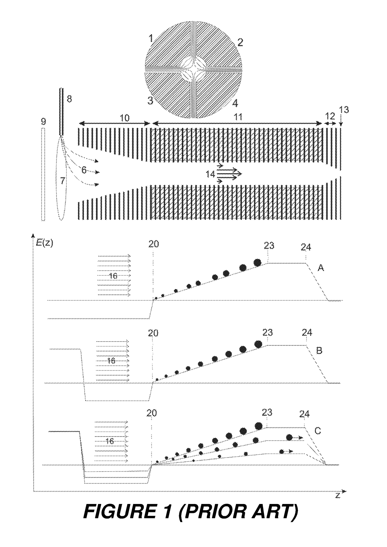
[0038]As shown in the lower portion of FIG. 6, the invention involves applying additional voltages to the electrodes (61) and (62) near the ends of the TIMS ion mobility separation tunnel (11) in order to generate a long and flat electric field ramp on which ions of an interesting range of mobilities only can be accumulated for the ion mobility scan. The flat field ramp is extended to almost the complete length of the tunnel, decompressing the density of the ion clouds and diminishing the effect of space charge. More ions can be collected on the flat ramp without severe losses, and the ions can then be measured with preselected ion mobility resolution by choosing the right scan speed.

[0039]Only ...


PUM


Abstract

The invention relates to the operation of ion mobility spectrometers based on gases pushing the ions over electrical field barriers, preferably in combination with mass spectrometers, and relates to trapped ion mobility spectrometers (“TIMS”). The invention proposes to accumulate and to scan the ions of a selected range of mobilities by using a long and flat electric field ramp created by additional voltages. By a voltage supplied at the beginning of the flat ramp, the lowest mobility of the mobility range of ions to be collected can be selected. By the difference of the voltages at the beginning and the end, the width of the mobility range is determined. The spatial zoom advantageously can collect considerable more ions of interest than a temporal zoom without severe losses by space charge effects, and more ions can be detected in the mass-mobility map.

Description

BACKGROUND OF THE INVENTION[0001]Field of the Invention[0002]The invention relates to methods and devices for the highly sensitive acquisition of high resolution ion mobility spectra.[0003]Description of the Related Art[0004]In document U.S. Pat. No. 7,838,826 B1 (M. A. Park, 2008), a small ion mobility spectrometer is presented. The length of the essential ion mobility scanning part, the ion mobility scanning tunnel, amounts to about five centimeters only; with additional entrance and exit funnels the device is less than ten centimeters long. The cylindrical ion mobility scanning tunnel comprises a quadrupolar RF field keeping the ions near the axis; separation of ions according to their mobilities is based upon a gas flow in the tunnel, driving the ions in an accumulation phase from an ion source against a ramp of an electric DC counter-field barrier. After shutting down the delivery of further ions, a scan phase starts, in which the field barrier is steadily decreased. Ions are d...

Claims


Application Information

Patent Timeline
Patent Type & Authority Patents(United States)
IPC IPC(8): H01J49/42
CPCH01J49/421H01J49/429G01N27/623
Inventor RATHER, OLIVERPARK, MELVIN ANDREW
Owner BRUKER DALTONICS INC
Why Eureka
Try Eureka