
System and method for automatically ramping down a superconducting persistent magnet

a technology of persistent magnets and automatic ramping, which is applied in the field of superconducting persistent magnets, can solve the problems of needing to be repaired or replaced, all the cryogenic fluid to evaporate and be lost, and heat damage to the magnet and/or other components of the system

Active Publication Date: 2018-05-29
KONINKLJIJKE PHILIPS NV
View PDF14 Cites 9 Cited by
  • Summary
  • Abstract
  • Description
  • Claims
  • Application Information

AI Technical Summary

Benefits of technology

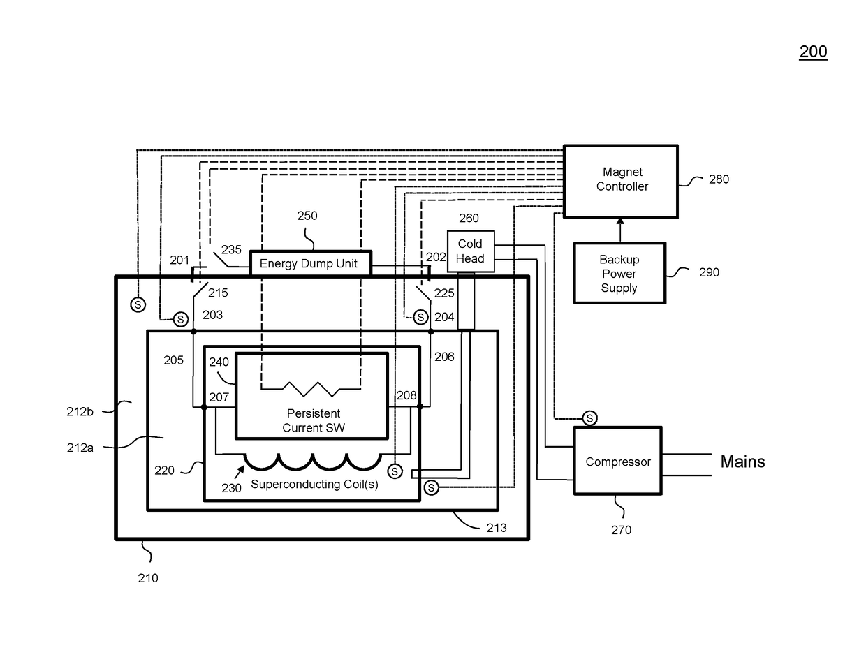
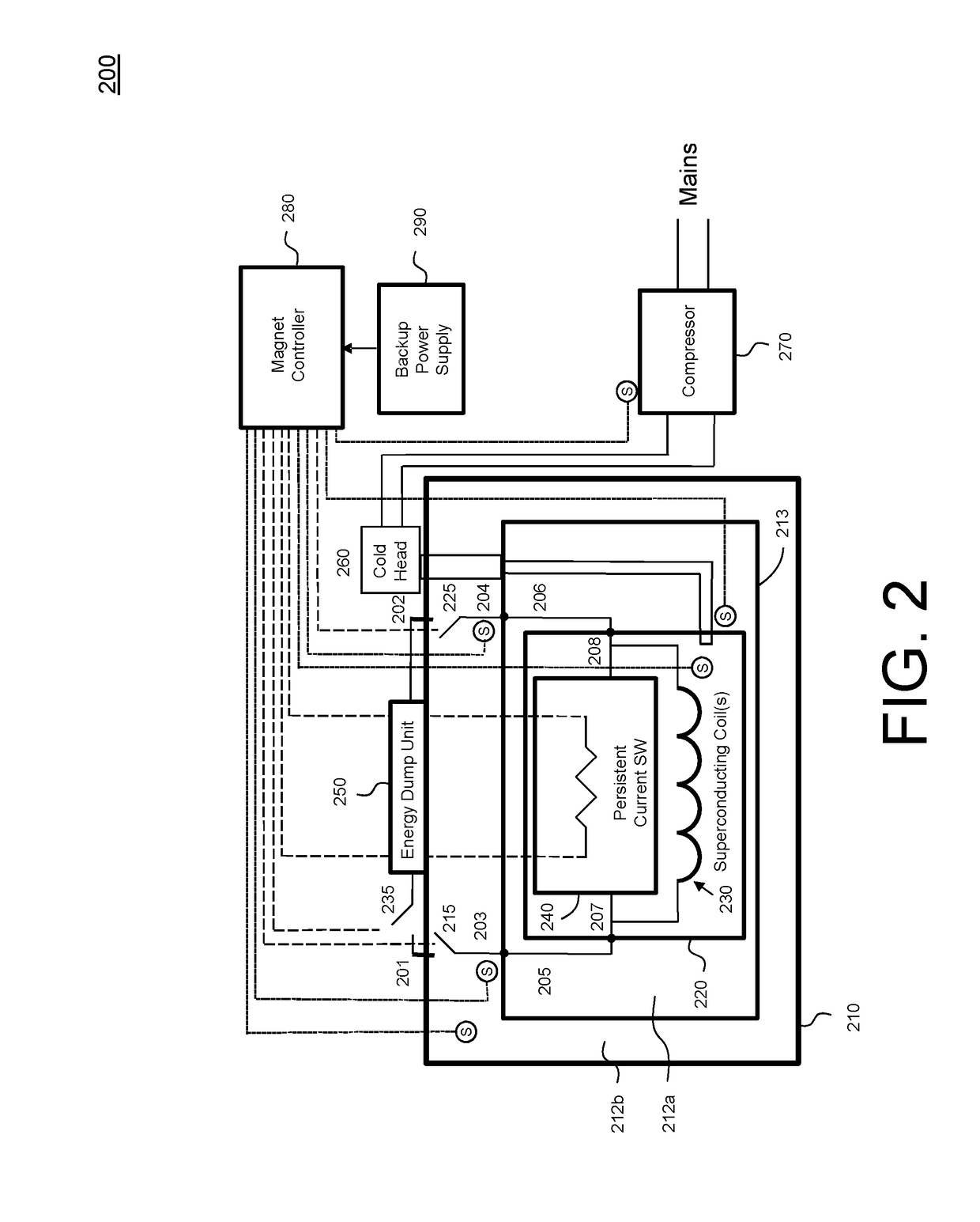
The patent describes an apparatus for preventing damage to a superconducting magnet system caused by power loss or quench. The apparatus includes an electrically conductive coil, a persistent current switch, a cryostat, an energy dump unit, and a magnet controller. The apparatus can detect and respond to operating faults, and can transfer energy from the electrically conductive coil to the energy dump unit to prevent damage to the magnet system. The apparatus can also include a cooling fan and retractable electrically conductive leads. The technical effect of the invention is to provide a reliable and cost-effective solution for preventing damage to superconducting magnet systems in the event of power loss or quench.

Problems solved by technology

This “quench” can cause some or all of the cryogenic fluid to evaporate and be lost, for example, through a pressure relieve valve.
Furthermore, the heat may damage the magnet and / or other components of the system.
Furthermore, if heat from the quench caused the magnet or other components to be damaged, they may need to be repaired or replaced.
This recovery process can be expensive and time-consuming.
Typically, a trained technician must be dispatched to the facility (e.g., a medical center or hospital) where the superconducting magnet system is located and new cryogenic fluid (e.g. liquid helium), which may be quite costly, must be supplied to the cryostat.
Nevertheless, MRI systems typically employ relatively large volumes of cryogenic fluid (e.g., 1000 liters of liquid helium), which can at least partially ameliorate such a situation.
However, some newer MRI systems employ so-called “cryofree” superconducting magnet systems which are closed or sealed and do not include any means for a user to add new cryogenic material to the system.
Accordingly, quench may occur in a relatively short amount of time (e.g., several hours) after a power failure to the compressor.
Furthermore, since the systems typically do not allow additional cryogens to be added, if the cryogenic liquid is degraded or evaporated due to a quench, recovery may not be possible.

Method used


Image

  • System and method for automatically ramping down a superconducting persistent magnet
  • System and method for automatically ramping down a superconducting persistent magnet
  • System and method for automatically ramping down a superconducting persistent magnet

Examples


Embodiment Construction

[0034]The present invention will now be described more fully hereinafter with reference to the accompanying drawings, in which preferred embodiments of the invention are shown. This invention may, however, be embodied in different forms and should not be construed as limited to the embodiments set forth herein. Rather, these embodiments are provided as teaching examples of the invention.

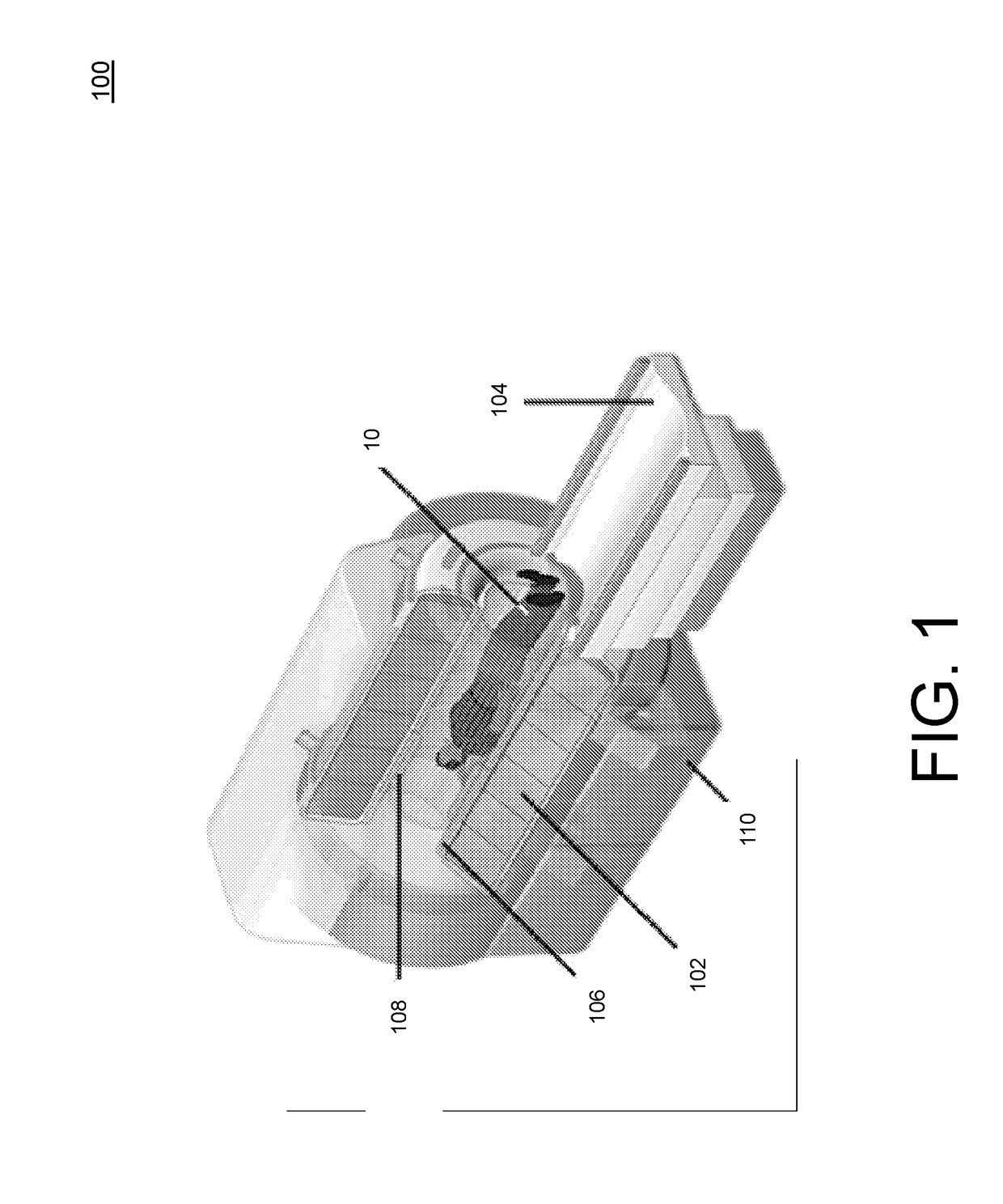
[0035]FIG. 1 illustrates one exemplary embodiment of a magnetic resonance imaging (MRI) apparatus 100. MRI apparatus 100 can include, for example, a magnet 102; a patient table 104 configured to hold a patient 10; gradient coils 106 configured to at least partially surround at least a portion of patient 10 for which MRI apparatus 100 generates an image; a radio frequency coil 108 configured to apply a radio frequency signal to at least the portion of patient 10 which is being imaged, and to alter the alignment of this magnetic field; and a scanner 110 configured to detect changes in the magnetic fiel...


PUM

PropertyMeasurementUnit
volumesaaaaaaaaaa
volumeaaaaaaaaaa
magnetic fieldaaaaaaaaaa

Abstract

An apparatus includes an electrically conductive coil which produces a magnetic field when an electrical current passes therethrough; a selectively activated persistent current switch connected across the electrically conductive coil; a cryostat having the electrically conductive coil and the persistent current switch disposed therein; an energy dump; at least one sensor which detects an operating parameter of the apparatus and outputs at least one sensor signal in response thereto; and a magnet controller. The magnet controller receives the sensor signal(s) and in response thereto detects whether an operating fault (e.g. a power loss to the compressor of a cryocooler) exists in the apparatus, and when an operating fault is detected, connects the energy dump unit across the electrically conductive coil to transfer energy from the electrically conductive coil to the energy dump unit. The energy dump unit disperses the energy outside of the cryostat.

Description

CROSS-REFERENCE TO PRIOR APPLICATIONS[0001]This application is the U.S. National Phase application under 35 U.S.C. § 371 of International Application No. PCT / IB2013 / 058693, filed on Sep. 20, 2013, which claims the benefit of U.S. Provisional Patent Application No. 61 / 706,160, filed on Sep. 27, 2012. These applications are hereby incorporated by reference herein.TECHNICAL FIELD[0002]This invention pertains to superconducting persistent magnets, and in particular, to a system and method for automatically ramping down a superconducting persistent magnet.BACKGROUND AND SUMMARY[0003]Superconducting magnets are typically used in a variety of contexts, including nuclear magnetic resonance (NMR) analysis and magnetic resonance imaging (MRI). To realize superconductivity, the magnet is maintained in a cryogenic environment at a temperature near absolute zero. Typically, the magnet comprises an electrically conductive coil which is disposed in a cryostat containing a volume of a cryogenic flu...

Claims


Application Information

Patent Timeline
Patent Type & Authority Patents(United States)
IPC IPC(8): H02H7/00H01F6/00G01R33/3815H01F6/02G01R33/38
CPCH02H7/001G01R33/3815H01F6/02H01F6/003G01R33/3804
Inventor JONAS, PHILIP ALEXANDERMULDER, GERARDUS BERNARDUS JOZEFVAN DER KOIJK, JOHANNES FERDINANDMOKHNATYUK, VIKTORPFLEIDERER, GLEN GEORGEMENTEUR, PHILIPPE ABELOVERWEG, JOHANNES ADRIANUSALLITT, MICHAEL LESLIEHUANG, XIANRUI
Owner KONINKLJIJKE PHILIPS NV
Learn More