Arrow tail lamp

a technology of arrows and tail lamps, which is applied in the direction of electric lighting with batteries, lighting elements, lighting and heating apparatus, etc., can solve the problems of shortened visual range, inconvenient use, and increased time consumed by lighting methods, and achieve convenient and quick use

Inactive Publication Date: 2018-06-05
MAI KANGLIN +1
View PDF4 Cites 3 Cited by
  • Summary
  • Abstract
  • Description
  • Claims
  • Application Information

AI Technical Summary

Benefits of technology

[0004]The technical problem solved by the novel arrow tail lamp according to the present invention is to provide an arrow tail lamp, which is convenient to turn off, is lightened depending on the inertia of shooting an arrow.
[0018]The novel arrow tail lamp provided by the invention has the beneficial effects that the inertial on-off loop, which is formed by the low voltage light source and the power supply through the inertia switch, is arranged in the shell. After the arrow tail lamp is arranged at the arrow tail, the inertia on-off loop can be accessed so that the low voltage light source gives out light due to inertia when a user shoots an arrow, and the shot arrow can be easily found out according to light beams on the arrow tail, so as to realize arrow recovery and prey tracking. The novel arrow tail lamp provided by the invention can be started depending on the inertia when the arrow is shot, therefore an arrow shooting process is a process of starting the novel arrow tail lamp; furthermore, after the user swings the arrow tail downwards, so that the disconnection of the closed circuit of the inertial on-off loop can be realized, and the novel arrow tail lamp is convenient and quick to use. The novel arrow tail lamp provided by the invention is used for the arrow tail lamp.

Problems solved by technology

However, an existing arrow tail lamp fundamentally needs to be lightened in advance before the arrow is shot, therefore this lightening way consumes more time, and the best opportunity of hunting is missed frequently under the condition that a prey is met suddenly.
Meanwhile, when the arrow is fitted to the string, eye pupils are shrunk due to the entering of light beams of the arrow tail when a person is close to the arrow tail to aim at the prey because the arrow tail gives out light, therefore the visual range is shortened and the person is not beneficial for aiming at a target.
Furthermore, the existing arrow tail lamp is troublesome to turn off.

Method used


Image

  • Arrow tail lamp
  • Arrow tail lamp
  • Arrow tail lamp

Examples


embodiment a1

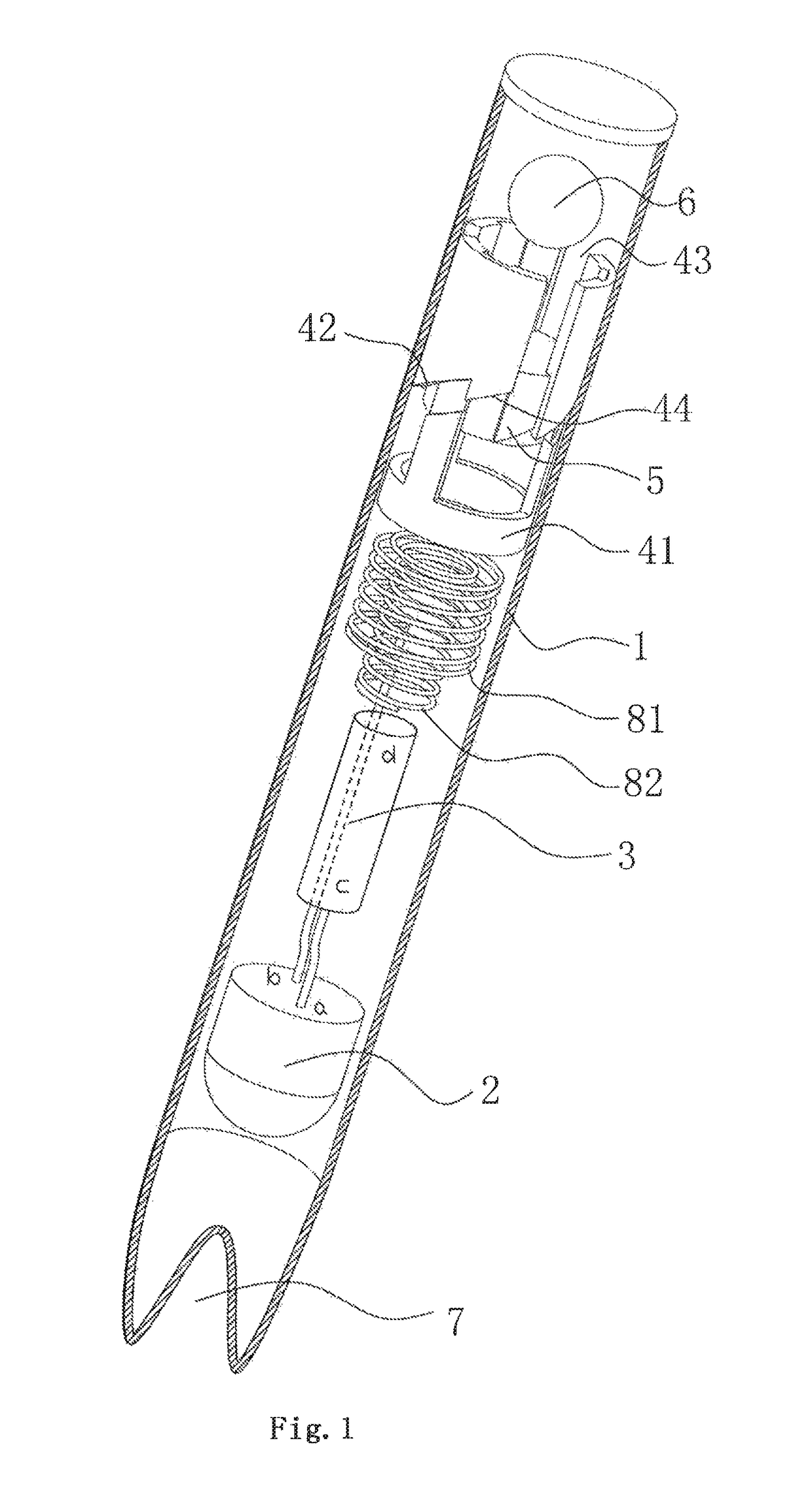
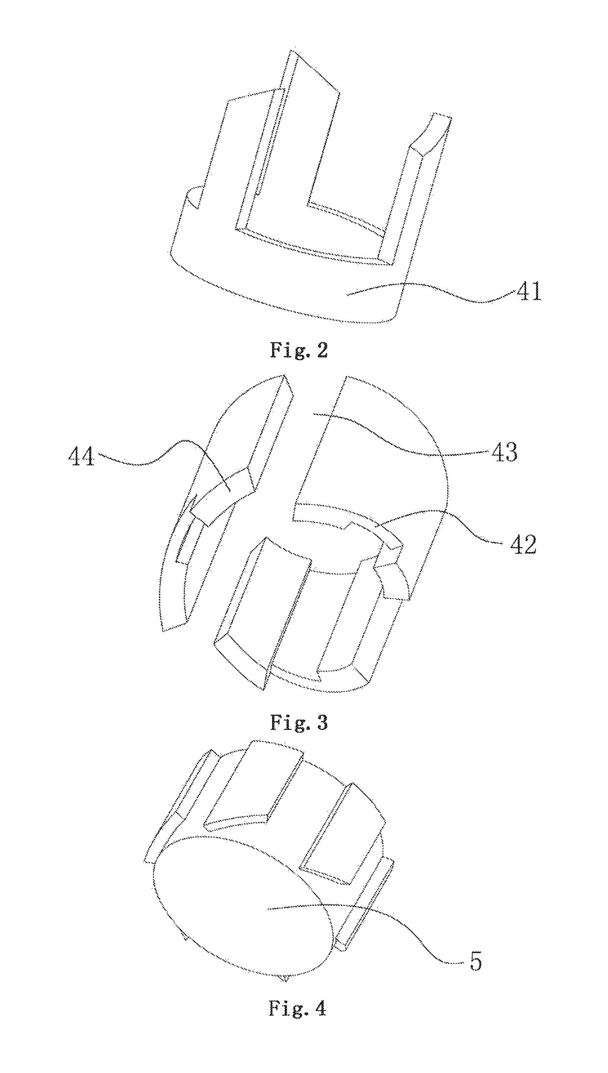
[0031]Referring to FIG. 1 to FIG. 8, an inner cavity of a shell 1 is provided with a low voltage light source 2 with an electrode a and an electrode b, the low voltage light source 2 is an LED (Light Emitting Diode) lamp bead, the electrode a is an anode of the LED lamp bead, and the electrode b is a cathode of the LED lamp bead. The electrode a of the low voltage light source is connected with an electrode c of a power supply 3, and the electrode c is an anode of the power supply 3; and the electrode d of the power supply 3 is a cathode. The electrode b is connected with an elastic component so that the electrode b is effectively connected with or separated from an electrode d for certain connecting strength or allowance. Three pushing parts 41, which are integrally connected, are arranged above the elastic component, three groups of locking parts 42 and guide parts 44 are distributed uniformly on the inner wall of the shell 1 above the pushing parts 41, and a gap, which is capable...

embodiment a2

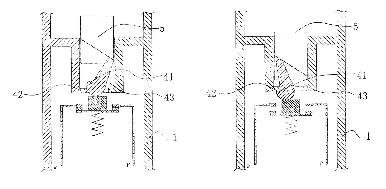
[0034]Referring to FIG. 9 to FIG. 10, an inertia switch of the embodiment a1 comprises pushing parts 41 and locking parts 42 arranged on a shell 1; the inertia switch further comprises reversing part 5, virtual connection parts 43 located below the reversing part 5 and an elastic component arranged below the pushing parts 41, wherein the virtual connection parts 43 are gaps located between the reversing part 5 and the locking parts 42, and the elastic component is springs; the inertia switch further comprises an electrode e and an electrode f which are respectively connected with a low voltage light source 2 and a power supply 3. FIG. 9 shows a structure chart of the connecting relationship of all parts of the inertia switch when the inertia on-off loop is a closed circuit, the reversing part 5 are driven by the downward inertia force so that the locking parts 42 of the virtual connection parts 43 contrarotate and move downwards when the novel arrow tail lamp is swung downwards, the...


PUM


Abstract

The invention discloses a novel arrow tail lamp, comprising an inertial on-off loop formed by the connection of a shell, a low voltage light source and an inertia switch, the inertial on-off loop can be switched between a closed circuit and an open circuit under the function that the inertia switch is functioned by the inertia in a same direction, and an inertial on-off loop formed by the low voltage light source and the power supply through the inertia switch, is arranged in the shell. The novel arrow tail lamp can be started depending on the inertia when the arrow is shot, therefore arrow shooting process is a process of starting the novel arrow tail lamp; furthermore, after the user swings the arrow tail downwards, the disconnection of the on inertial on-off loop can be realized, so that the novel arrow tail lamp is convenient and quick to use.

Description

CROSS REFERENCE TO RELATED APPLICATION[0001]This application claims priority to and the benefit of Chinese Patent Application No. 201520748216.6 filed in the Chinese Intellectual Property Office on Sep. 23, 2015, the entire contents of which are incorporated herein by reference.FIELD OF THE INVENTION[0002]The invention relates to a novel arrow tail lamp.BACKGROUND OF THE INVENTION[0003]Many people like hunting by arrows at night, specifically for those abroad. In order to be convenient for getting back the shot arrows, the arrow tail lamps are frequently arranged on arrow tails. However, an existing arrow tail lamp fundamentally needs to be lightened in advance before the arrow is shot, therefore this lightening way consumes more time, and the best opportunity of hunting is missed frequently under the condition that a prey is met suddenly. Meanwhile, when the arrow is fitted to the string, eye pupils are shrunk due to the entering of light beams of the arrow tail when a person is cl...

Claims


Application Information

Patent Timeline
Patent Type & Authority Patents(United States)
IPC IPC(8): F21L4/00F21V23/04F42B12/40F42B12/38F42B6/06F21V33/00
CPCF21V23/0492F21V33/008F42B12/40F42B12/382F42B6/06
Inventor MAI, KANGLINZHONG, YAOFEN
Owner MAI KANGLIN
Why Eureka
Try Eureka