Crankcase ventilation device for vehicle
- Summary
- Abstract
- Description
- Claims
- Application Information
AI Technical Summary
Benefits of technology
Problems solved by technology
Method used
Image

Examples
Embodiment Construction
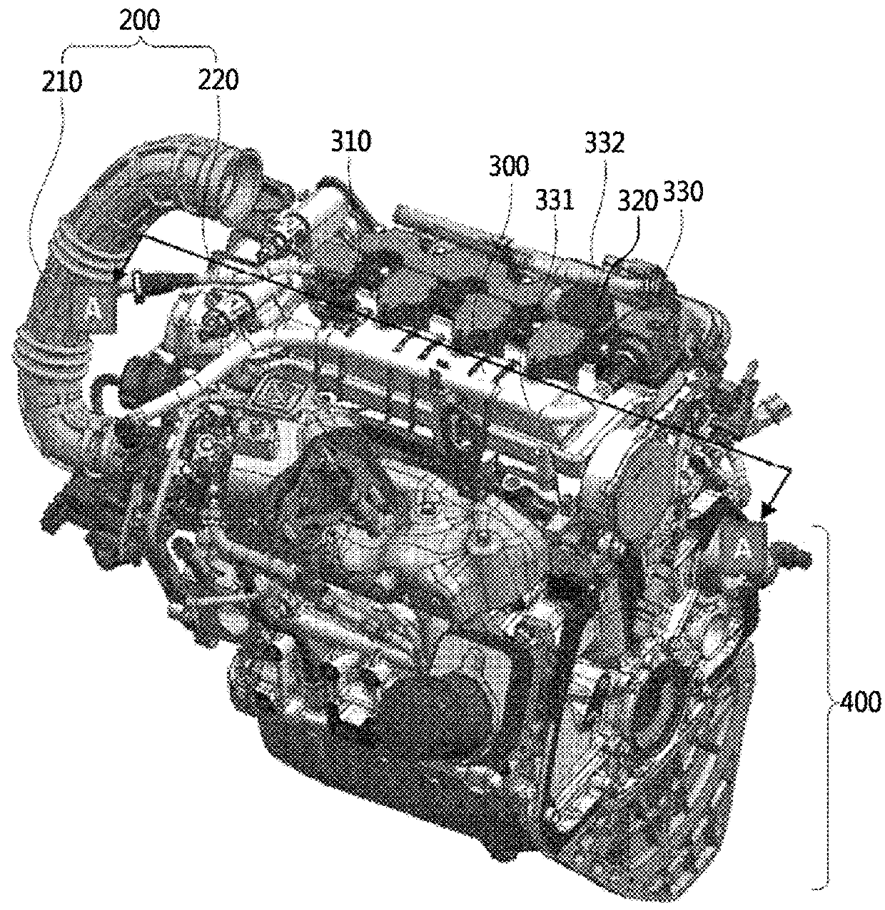
[0019]FIG. 1 is a perspective view illustrating the entire external appearance of a crankcase ventilation device 1000 for a vehicle according to an embodiment of the present invention.
[0020]FIG. 2 is a sectional view of the crankcase ventilation device 1000 for a vehicle taken along line A-A of FIG. 1.
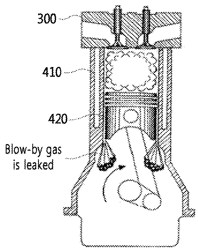
[0021]FIG. 3A and FIG. 3B are views illustrating generation of a blow-by gas in the interior of a crankcase 400.
[0022]FIG. 4 is a sectional view of a fresh air inflow control valve 310.
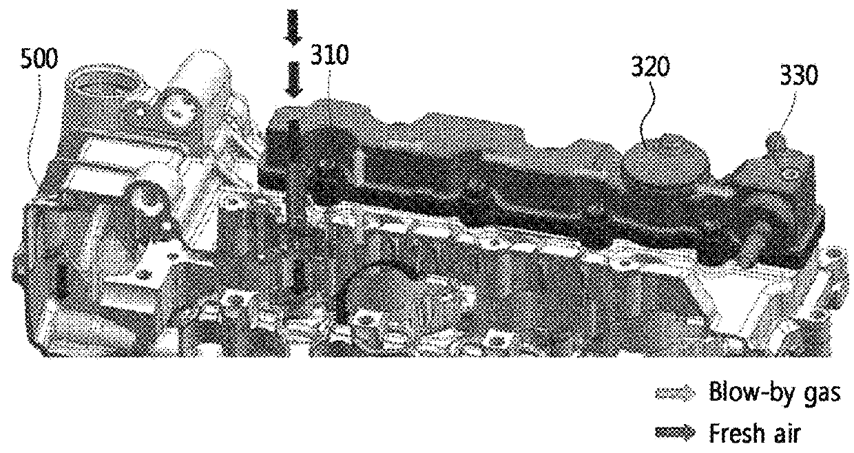
[0023]FIG. 5 is a view illustrating flows of a fresh air and a blow-by gas of the crankcase ventilation device 1000 under a low-speed / middle-speed condition.
[0024]FIG. 6 is a view illustrating flows of a fresh air and a blow-by gas of the crankcase ventilation device 1000 under a high-speed condition.
BEST MODE
[0025]The elements constituting the crankcase ventilation device for a vehicle according to the present invention may be integrally used or separately used as occasion demands. Further, some element...
PUM
 Abstract
Description
Claims
Application Information