
Actuator pivot shaft rolling bearing with seal

a technology of rolling bearing and pivot shaft, which is applied in the direction of bearing components, shafts and bearings, gas turbine plants, etc., can solve the problems of reducing the available vtg actuation torque, affecting the operation of the actuating shaft, so as to reduce the friction, reduce the rolling resistance, and reduce the friction

Active Publication Date: 2014-02-04
BORGWARNER INC
View PDF2 Cites 3 Cited by
  • Summary
  • Abstract
  • Description
  • Claims
  • Application Information

AI Technical Summary

Benefits of technology

The text describes a special type of bearing that uses tiny rolling elements to carry heavy loads. These elements move smoothly and with very little friction. This type of bearing can be designed to have very little movement in the axial and radial directions, which makes it ideal for sealing applications. The text also explains that the position and surface finish of the bearing races can be carefully controlled to improve performance. Overall, the patent text describes a new technology that reduces friction and improves the performance of bearings.

Problems solved by technology

Other VTG actuator pivot shafts can experience significant wear in certain applications during operation, presumably from high pressure loading between the bushing and shaft near the fork end of the shaft (turbine side).
Lack of lubrication can cause high friction forces between the shaft and bearing components, reducing available VTG actuation torque.
Furthermore, in certain operations, it may be difficult to seal the shaft to the bearing housing because of clearance between the shaft and bushing and the associated misalignment of the shaft to the bushing / housing.

Method used


Image

  • Actuator pivot shaft rolling bearing with seal

Examples


Embodiment Construction

[0016]A turbocharger is generally known and includes a turbine and a compressor, wherein a compressor impeller is rotatably driven via a rotating shaft by a turbine wheel. The rotating shaft passes through a bearing housing between a turbine housing and a compressor housing.

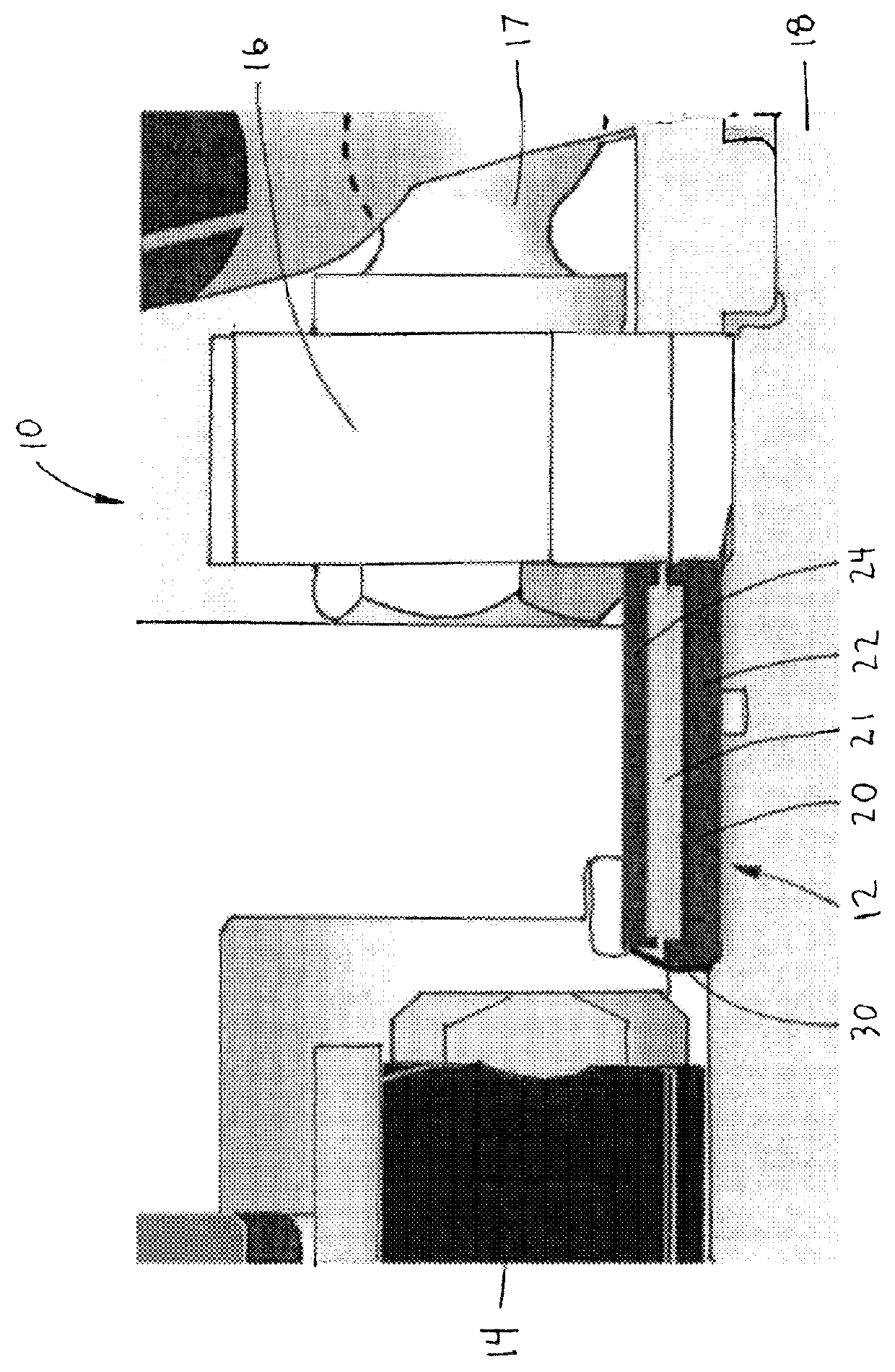
[0017]The variable turbine geometry (VTG) turbocharger 10 may include an actuator pivot shaft assembly 12 as shown in FIG. 1 with a portion between a large block 14 and a VTG lever 16 with a ball 17 on the VTG lever 16. The actuator pivot shaft 18 defines an axis of rotation partially surrounded by a rolling-element bearing 20.

[0018]The VTG turbocharger 10 may include an actuator pivot shaft bearing assembly 12 with a rolling-element bearing 20 with a rolling element 21 between an inner race 22 and outer race 24. The inner race 22 is closest to the actuator pivot shaft 18 with a smaller circumference than the outer race 24. The rolling elements 21 used in rolling-element bearings 20 is shown in the figure as a cy...


PUM


Abstract

A variable turbine geometry turbocharger with an actuator pivot shaft with a rolling-element bearing having a rolling element between an inner race and outer race. Replacing a standard actuator shaft bushing with a rolling-element bearing may reduce friction and adverse movement in certain applications. Various seals may be feasible, such as a face seal attached to the inner or outer bearing race that could seal against the opposing race.

Description

BACKGROUND[0001]1. Field of the Disclosure[0002]This disclosure relates to turbochargers with variable turbine geometry with an actuator pivot shaft. Specifically, this disclosure relates to replacing a standard actuator shaft bushing with a rolling-element bearing.[0003]2. Description of Related Art[0004]Advantages of turbocharging include increased power output, lower fuel consumption and reduced pollutant emissions. The turbocharging of engines is no longer primarily seen from a high-power performance perspective, but is rather viewed as a means of reducing fuel consumption and environmental pollution on account of lower carbon dioxide (CO2) emissions. Currently, a primary reason for turbocharging is using exhaust gas energy to reduce fuel consumption and emissions. In turbocharged engines, combustion air is pre-compressed before being supplied to the engine. The engine aspirates the same volume of air-fuel mixture as a naturally aspirated engine, but due to the higher pressure, ...

Claims


Application Information

Patent Timeline
Patent Type & Authority Patents(United States)
IPC IPC(8): F01D25/16
CPCF01D25/16F05D2240/50F02C6/12F01D17/20
Inventor KENNEDY, DONALD, MICHAEL
Owner BORGWARNER INC
Learn More