
Heavy-duty tire

a tire and heavy-duty technology, applied in the field of heavy-duty tires, can solve the problems of reducing block rigidity, difficult to sufficiently improve the wet performance of the tire, and uneven wear resistance, and achieves excellent wet performance, small rolling resistance, and high rigidity.

Active Publication Date: 2016-06-09
SUMITOMO RUBBER IND LTD
View PDF5 Cites 17 Cited by
  • Summary
  • Abstract
  • Description
  • Claims
  • Application Information

AI Technical Summary

Benefits of technology

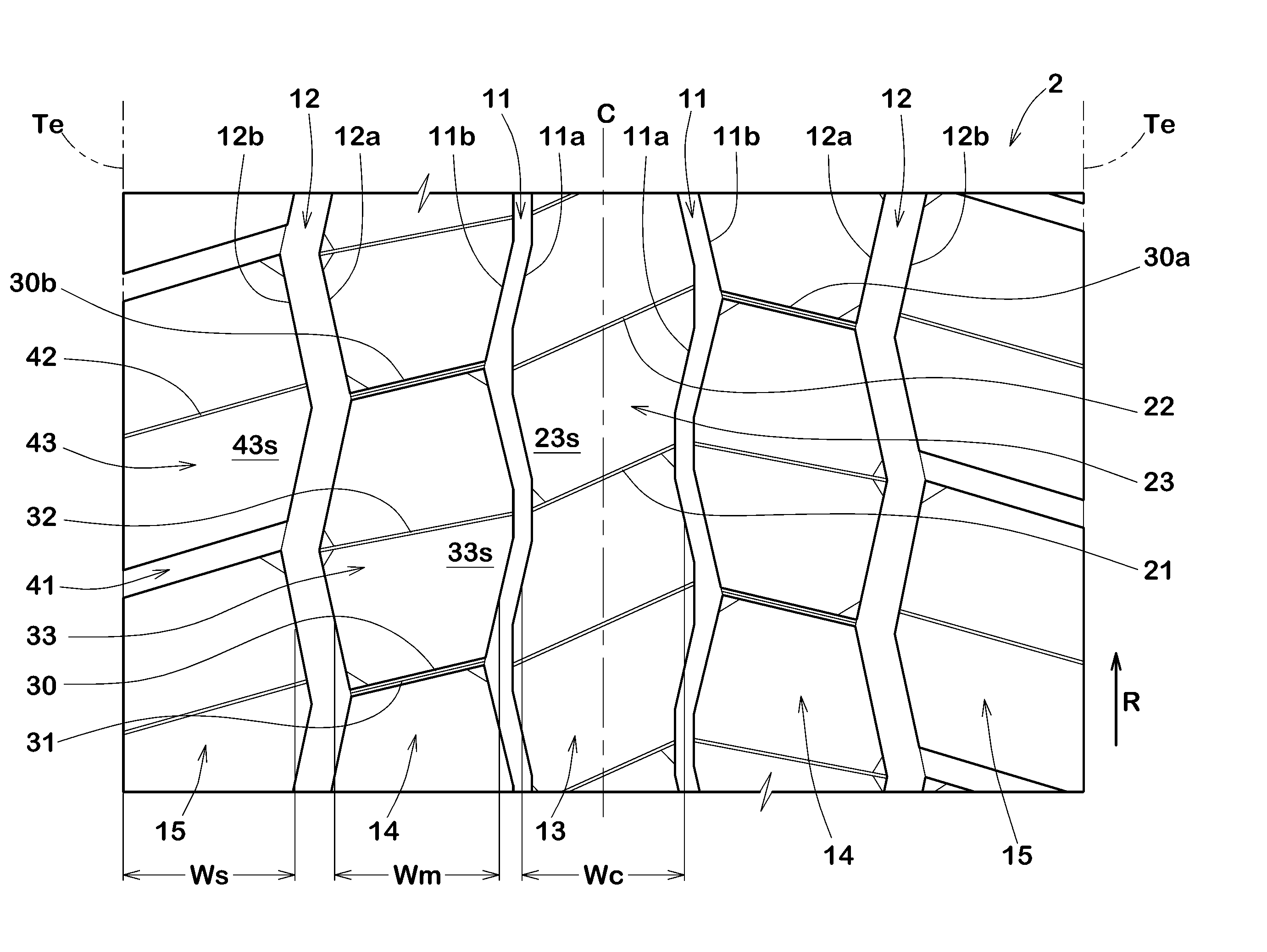
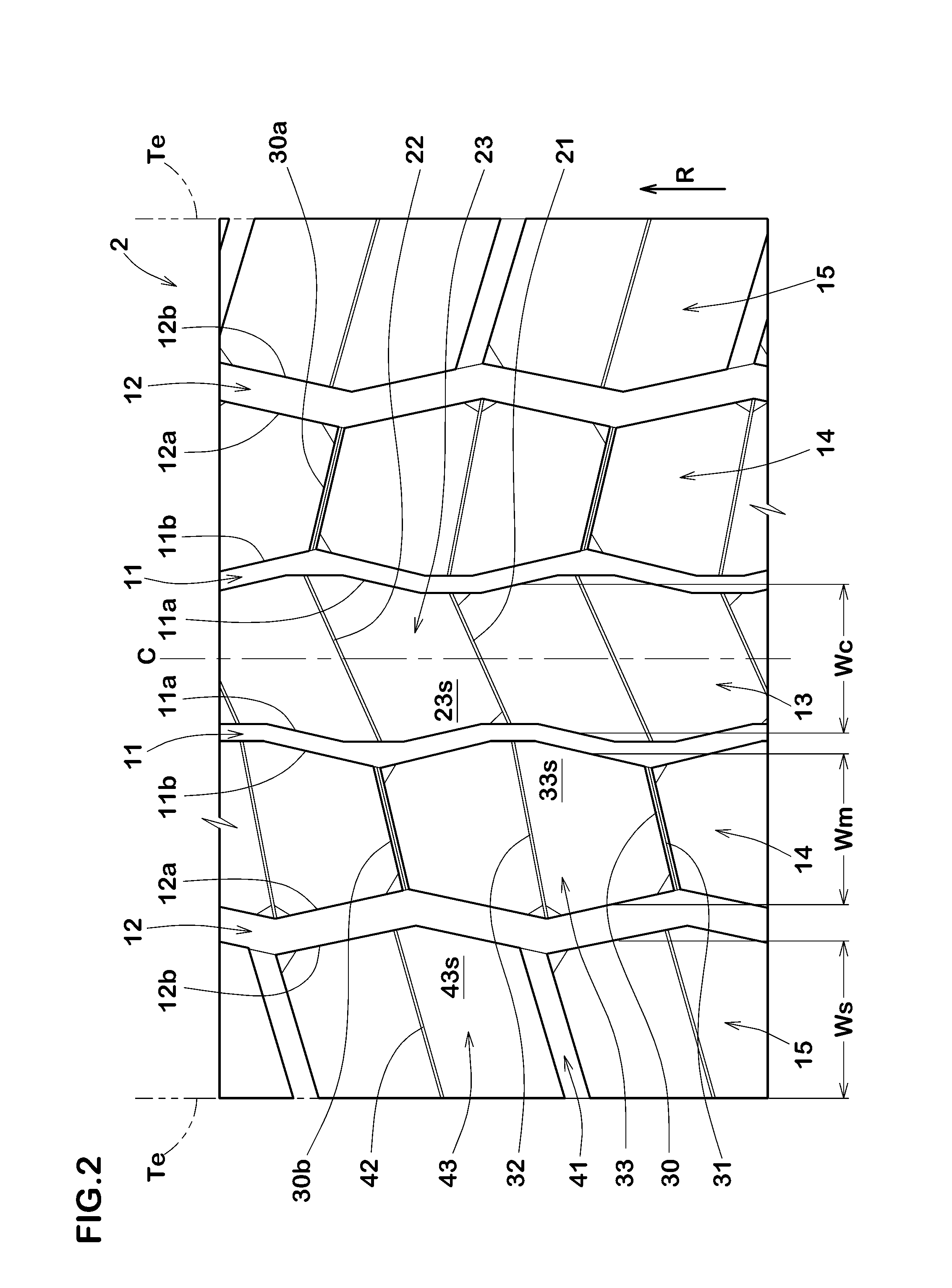
The present invention is about a heavy duty tire. This tire has innovative design features that improve its performance. Firstly, the middle land portion of the tire is divided into small blocks using zigzag center main grooves, shoulder main grooves, and adjacent middle lateral shallow grooves and sipes. This design increases the rigidity of the middle land portion and improves its wear resistance. Secondly, the middle lateral shallow grooves and first middle lateral sipes improve the drainage performance of the middle land portion and help control the movements of the blocks in ground contact. This helps to prevent uneven wear of the tire. Overall, this innovation makes the tire more durable and efficient.

Problems solved by technology

In the heavy duty tire disclosed in the Patent Document 1, however, since the depth of the lateral grooves is 80% to 90% of the depth of the main grooves, there is a possibility that the block rigidity decreases, and it is difficult to sufficiently improve the rolling resistance and uneven wear resistance.
Further, the drainage capacity of the main grooves extending in a zigzag shape of the heavy duty tire disclosed in the Patent Document 1 has a tendency to become insufficient when compared with main grooves extending straight, therefore, it is difficult to sufficiently improve the wet performance of the tire.
Furthermore, in the heavy duty tire disclosed in the Patent Document 2, the ground contact pressure is concentrated on the edges of the blocks, and uneven wear such as heel-and-toe wear in which that portion wears prematurely is liable to occur.
This tire has a problem of having a low wet performance.

Method used


Image

  • Heavy-duty tire
  • Heavy-duty tire
  • Heavy-duty tire

Examples


working examples

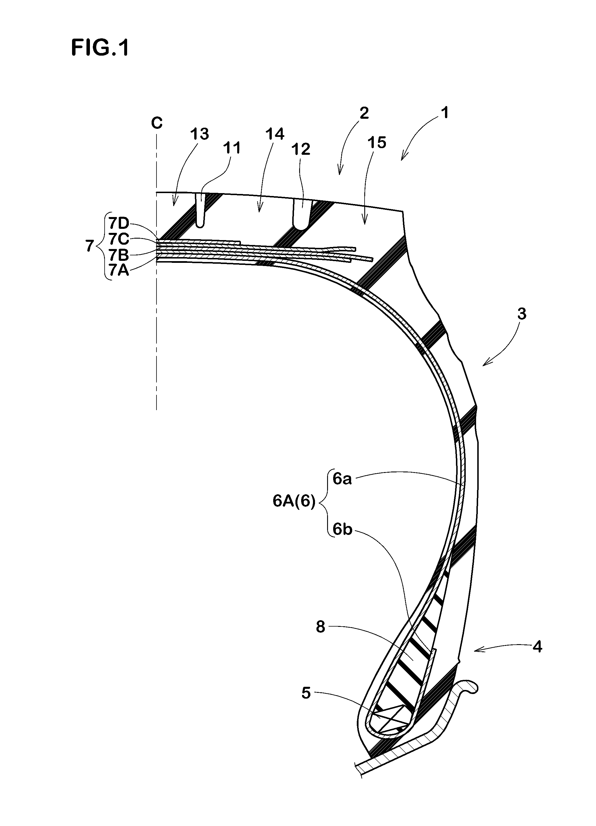
[0159]Heavy duty tires of size 315 / 80R22.5 having the basic structure shown in FIG. 1 were experimentally manufactured based on specifications shown in Tables 1 to 4, and tested for the rolling resistance, wet performance and uneven wear resistance under conditions of internal pressure 850 kPa and rim 22.5×9.00.

[0160]Testing methods were as follows.

[0161]Using a rolling resistance tester, the rolling resistance of each test tire was measured at a speed of 80 km / h and a load of 33.34 kN. The result is an index based on working example 1 being 100, wherein the large the value, the smaller the rolling resistance, which means that the fuel efficiency is better.

[0162]Each test tire was mounted on every wheel of a truck (2-D vehicle) with a maximum loading capacity of 10 tons.

The vehicle in a semi-loaded state (loaded in a front of the loading platform) was brought into a wet asphalt road surface with a water film having 5 mm thickness. Then, the clutch was connected, keeping the engine s...


PUM


Abstract

A tread portion (2) has a pair of center main grooves (11) extending zigzag and continuously in a tire circumference direction, a pair of shoulder main grooves (12), a center land portion (13), a pair of middle land portions (14), and a pair of shoulder land portions (15). The center main groove (11) has a first groove edge (11a) on the tire equator side and a second groove edge (11b) on the tread edge side. The shoulder main groove (12) has a third groove edge (12a) on the tire equator side and a fourth groove edge (12b) on the tread edge side. The middle land portion (14) is provided with a plurality of middle lateral shallow grooves (30) connecting between apex portions (11h) on the most tread edge side of the second groove edge (11b) and apex portions (12c) on the most tire equator side of the third groove edge (12a); and a plurality of first middle lateral sipes (31) extending along the middle lateral shallow grooves (30) at the groove bottoms of the middle lateral shallow grooves (30) and connecting between the center main groove (11) and the shoulder main groove (12).

Description

TECHNICAL FIELD[0001]The present invention relates to a heavy duty tire improved in uneven wear resistance.BACKGROUND[0002]In a heavy duty tire for use with trucks, buses and the like, the tread portion is conventionally provided with a plurality of main grooves extending in the tire circumferential direction and a plurality of lateral grooves extending in the tire axial direction. By these grooves, various performances required for the tire such as wet performance, rolling resistance and uneven wear resistance are enhanced.[0003]For example, in the following Patent Document 1, there is disclosed a heavy duty tire provided in the tread portion with hexagonal blocks divided by a plurality of main grooves extending in a zigzag shape (circumferential grooves 10, 11 and circumferential narrow groove 24 in the document), and a plurality of lateral grooves (lug grooves 25, 26, 27 in the document). Such tire can reduce tire noise, while improving wet performance and uneven wear resistance....

Claims


Application Information

Patent Timeline
Patent Type & Authority Applications(United States)
IPC IPC(8): B60C11/03B60C11/12B60C11/13
CPCB60C11/033B60C11/0309B60C11/1353B60C11/125B60C11/1259B60C2011/0334B60C11/0304B60C2011/0346B60C2011/0372B60C2011/0367B60C11/1236B60C2200/06B60C11/0306B60C2011/1209
Inventor WASHIZUKA, MASAKAZUTODOROKI, DAISUKEMAEHARA, ATSUSHI
Owner SUMITOMO RUBBER IND LTD
Learn More