Signal conditioning apparatus

a signal conditioning and apparatus technology, applied in the direction of current interference reduction, differential amplifiers, amplifiers with semiconductor devices/discharge tubes, etc., can solve the problems of interference between the fidelity of signals being conveyed over conductors, the source of many types of electrical interference, and the fidelity of signals being conveyed. to achieve the effect of less costly and more efficien

Inactive Publication Date: 2001-04-10
FIORI JR DAVID
View PDF15 Cites 39 Cited by
  • Summary
  • Abstract
  • Description
  • Claims
  • Application Information

AI Technical Summary

Benefits of technology

It is an objective of the present invention to provide various types of electronic circuits including amplifier systems, such as audio, power and video amplifier systems, with circuitry to suppress or eliminate the expression of all types of interference in the wiring conveying analog voltage potential signals from a source to a destination. This is accomplished in the present invention by the unique combination of novel interference rejection circuits that address the sources of interference in these systems in a less costly and more efficient manner than other approaches.
A further objective of the present invention is to provide for the conditioning of differential signals, or any number of signals, where each signal is produced with reference to independent potential references which make higher levels of interference rejection possible.

Problems solved by technology

Conductors that provide electrical connection between devices in a system are often the source of many types of electrical interference.
Magnetic fields, electric fields and electro-magnetic or radio frequency fields are known to interfere with the fidelity of signals conveyed over conductors which are subjected to those fields.
Furthermore, the ground or reference conductor of a typical signal carrying pair of conductors are often connected to different local ground potentials between one end of the conductor as compared to the other, and currents are known to flow in such conductors which then produce voltage drops on that conductor which also interfere with the fidelity of the signals being conveyed.
In addition, these conductors, especially when very long, present loads to the signal source that may adversely effect the fidelity of the signal.
The conveyance of signals, especially between powered devices, is often plagued by electro-magnetic interference.
Such approaches, while effective, can be very costly, and require extensive circuitry at both the sending and receiving ends of the conductors.
This approach, while effective in eliminating most interference is nevertheless expensive and difficult to implement.
Multiple conductors are also required to be contained within a single shield, which is more costly than conductors having only one conductor surrounded by a shield.
Such methods do not, however, address any interference or other affects of the cables that connect the transmitter and receiver to source and destination respectively.
Because it is common for there to be multiple electronic paths between the reference potentials of each subsystem, and since such paths commonly include sources of interference, these alternative paths are often responsible for the interference present in those systems.
However, such an approach is not easily adapted to electronic systems consisting of single ended two wire signal conductors.
Consequently, this approach suffers from the same limitations as devices that convey signals by differential means.
Moreover, Morrison does not address the pickup of electric field interference or any other cable affects due to the output cable.
In particular the output impedance of the opamps used to determine A1 will negatively impact the interference rejection of any common mode voltage differences between source and destination reference potentials as that impedance relates to the difference resistors of gain stage A2.
As this circuit characteristic is extremely gain and temperature dependent, such inaccuracies are not easily controlled without increased expense in the design of the output stages of those circuits or without compromises inherent in the utilization of higher impedances than would be appropriate in achieving other performance objectives such as thermal noise and bandwidth which are adversely affected by higher resistor values in this case.

Method used


Image

  • Signal conditioning apparatus
  • Signal conditioning apparatus
  • Signal conditioning apparatus

Examples


Embodiment Construction

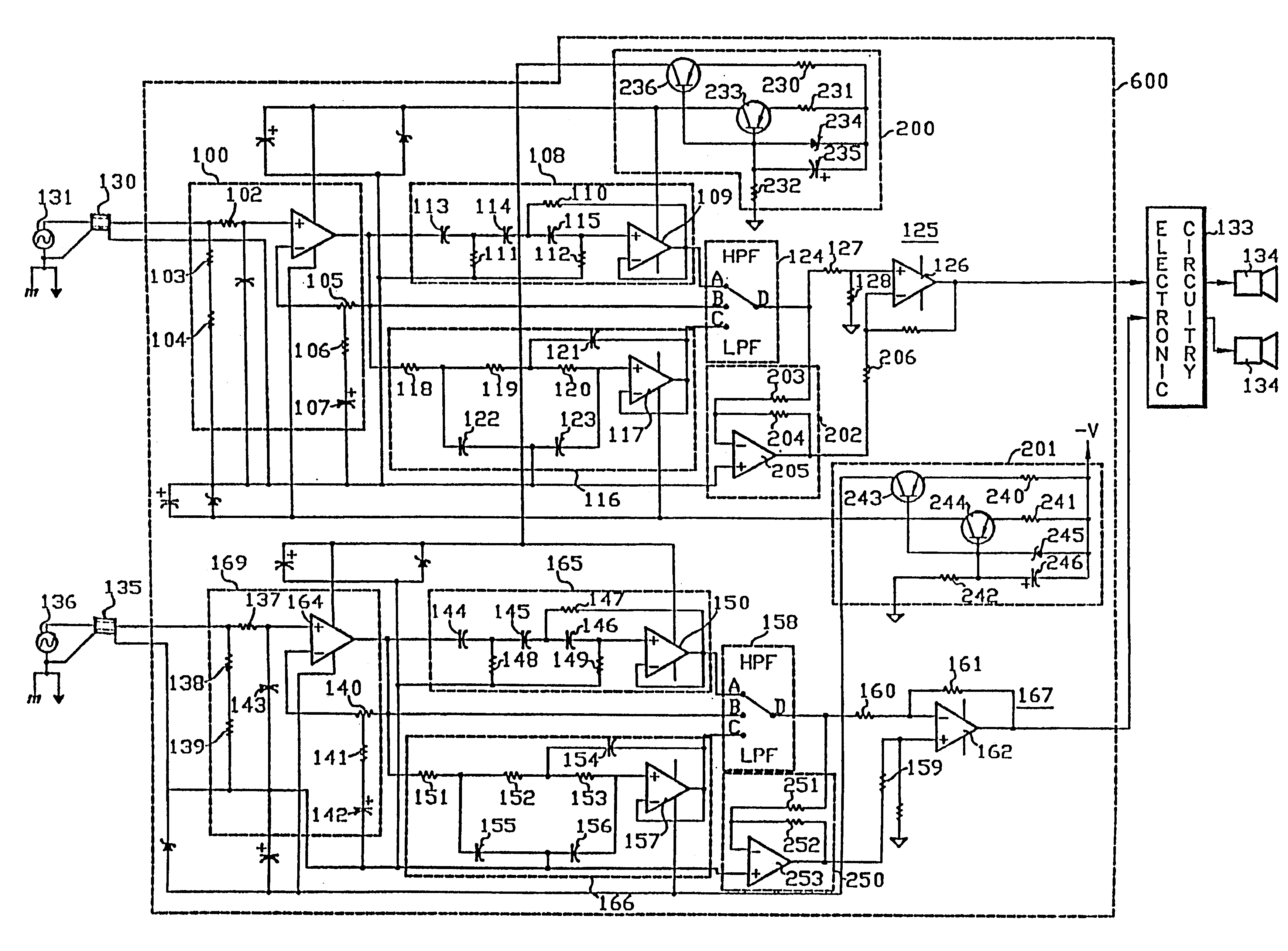
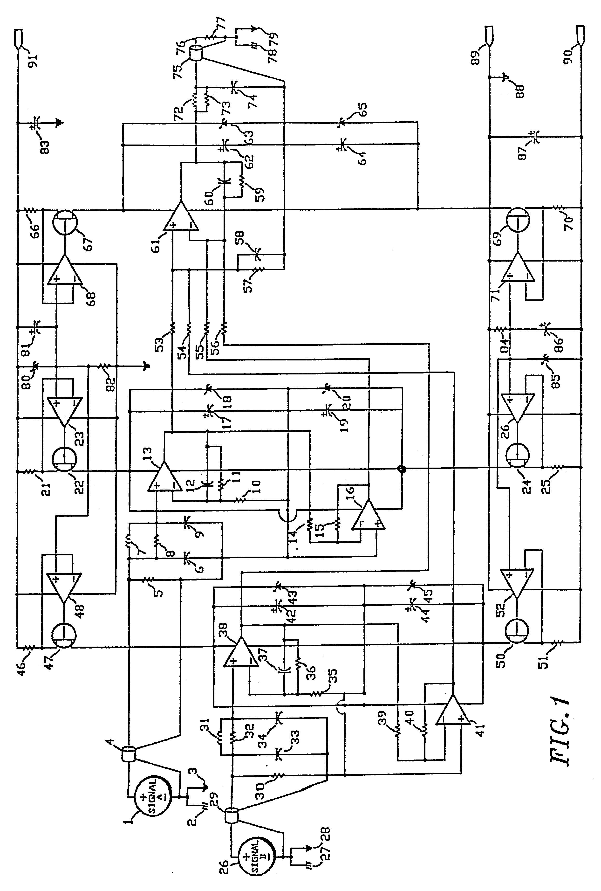
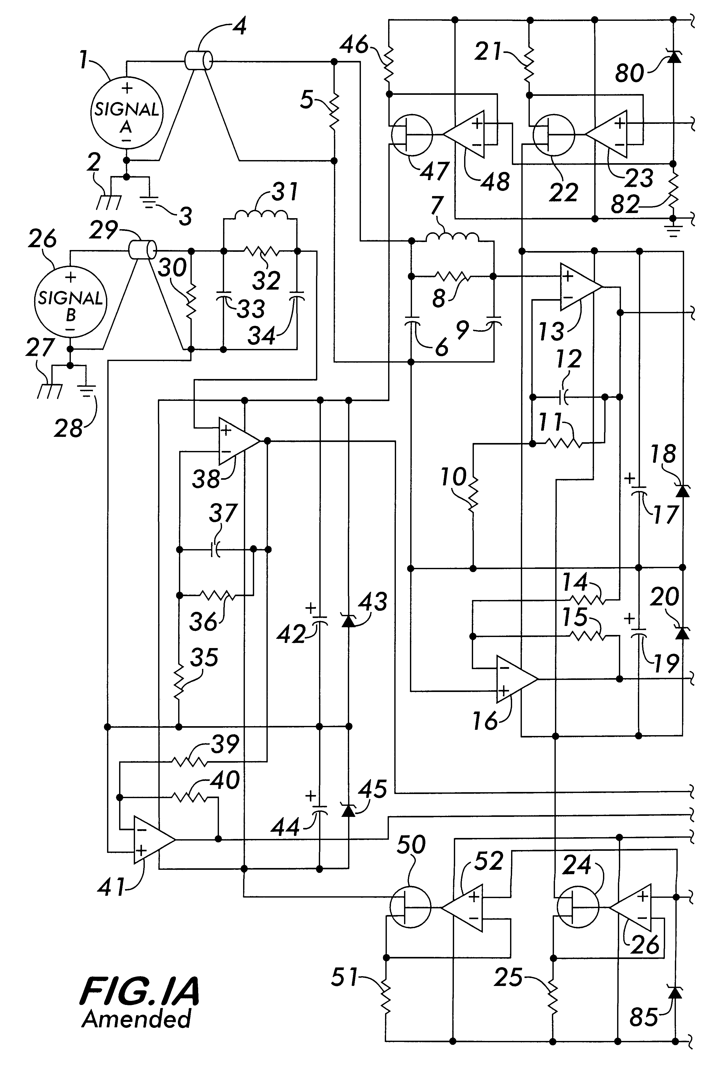
Referring to the drawings, in which like reference numerals identify identical or similar elements, and in particular to .[.FIG. 1.]. .Iadd.FIGS. 1A and 1B.Iaddend., signal source 1 may be understood to be differentially related to signal source 26 in instances where signal 1 and signal 26 are both available and known to relate to each other in an arithmetically inverse manner. Such a relationship is not necessary to carry out the present invention. Other relationships may be appropriate; indeed, if the circuit were to be used as a mixer of signals, there may be no relationship at all. Also, signal 1 or signal 26 need not convey a signal at all, and either may be disconnected to apply the device to single ended signals utilizing only two conductors to convey a signal, without limiting the effectiveness of the device.

Signal 1 and Signal 26 are conveyed over coaxial cable(s) 4 and 29 respectively. Coaxial cables are preferred in connection with this invention because the coaxial natur...


PUM


Abstract

A signal conditioning system that receives inputs from at least one pair of conductors connected to its input. Each such input is processed by an input filter and presented to a buffer amplifier. Each such input filter and buffer amplifier refers to and is powered by independent power sources whose power return reference potentials are independently determined by the potential of the corresponding input signal potential reference conductor for the signal frequencies of interest. The outputs of all such buffer amplifiers, the power return reference potentials, and the power return reference potential of the conditioning circuit output are all appropriately added or subtracted in the next circuit stage. This circuit stage consists of an amplifier buffer having low output impedance which is powered by another independent power source whose power return reference potential is independently determined by the potential of the output signal reference conductor. The output of this circuit stage is connected to an output inductor circuit which in turn drives the output signal conductor. The output includes a filter, and is designed to decouple unstable loading conditions while rejecting external influences on the output signal. The invention also includes means that connect the reference potential of the destination of the output conductors to the system power ground potential. The present invention provides a relatively inexpensive and efficient way of reducing or eliminating interference caused by coax cabling in audio, power and video amplifiers, for example.

Description

BACKGROUND OF THE INVENTION1. Field of the InventionThe present invention relates to circuits that use signal conditioning circuitry to eliminate interferences caused by magnetic fields, electric fields, and electro-magnetic or radio frequency fields on conductors that provide electrical connection between devices in a system. The present invention also relates to various electronic circuit that drive conductors, the electronic circuits including signal conditioning circuit to overcome the adverse effects of their loading on the signal source. More specifically, the present invention relates to audio amplifiers, power amplifiers, video amplifiers, etc. that use signal conditioning circuitry for achieving the above-noted benefit.2. Description of Related ArtConductors that provide electrical connection between devices in a system are often the source of many types of electrical interference. Magnetic fields, electric fields and electro-magnetic or radio frequency fields are known to ...

Claims


Application Information

Patent Timeline
Patent Type & Authority Patents(United States)
IPC IPC(8): H03F3/68H03F3/189H03F3/195H04B3/02H04B3/28
CPCH03F3/195H03F3/68H04B3/28
Inventor FIORI, JR., DAVID
Owner FIORI JR DAVID
Why Eureka
Try Eureka