Ocular optics system having at least four reflections occurring between curved surfaces

Inactive Publication Date: 2001-05-08
OLYMPUS OPTICAL CO LTD
11 Cites 29 Cited by

AI-Extracted Technical Summary

Problems solved by technology

A problem associated with an image display device of the type wherein an image thereof is relayed as shown in FIG. 6 is, however, that it needs not only an ocular optical system, but also a relay optical system, resulting in increases in the size and weight of the whole optical system as well as an increase in the amount of extension of the whole optical system from a person's head or face.
Therefore it is not fit for a head-mounted or face-mounted image display device.
The optical system for forming parallel beams as an intermediate image as well as the...

Benefits of technology

In view of such problems associated with the prior art as mentioned above, an object of the present invention is to provide an ocular optical system designed to form no intermediate image...

Abstract

The invention relates to an ocular optics system which forms no intermediate image, is reduced in terms of size and weight with well-corrected aberrations, and is best suited for use on face- or head-mounted image display devices, and provides an ocular optics system 7 comprising three juxtaposed optical surfaces 3, 4 and 5, wherein a space defined by three optical surfaces 3, 4, and 5 is filled with a transparent medium having a refractive index greater than 1, at least two optical surfaces 3 and 4 of these three optical surfaces are defined by curved surfaces concave on a pupil position side of the optics system, and at least four reflections occur between curved surfaces 3 and 4.

Application Domain

Magnifying glasses

Technology Topic

Image

  • Ocular optics system having at least four reflections occurring between curved surfaces
  • Ocular optics system having at least four reflections occurring between curved surfaces
  • Ocular optics system having at least four reflections occurring between curved surfaces

Examples

  • Experimental program(4)

Example

Examples 1 to 3 
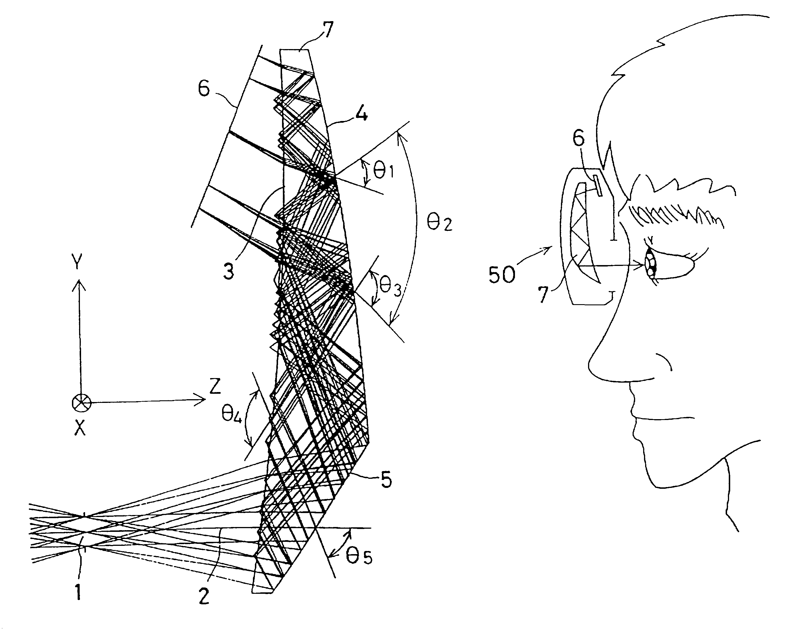
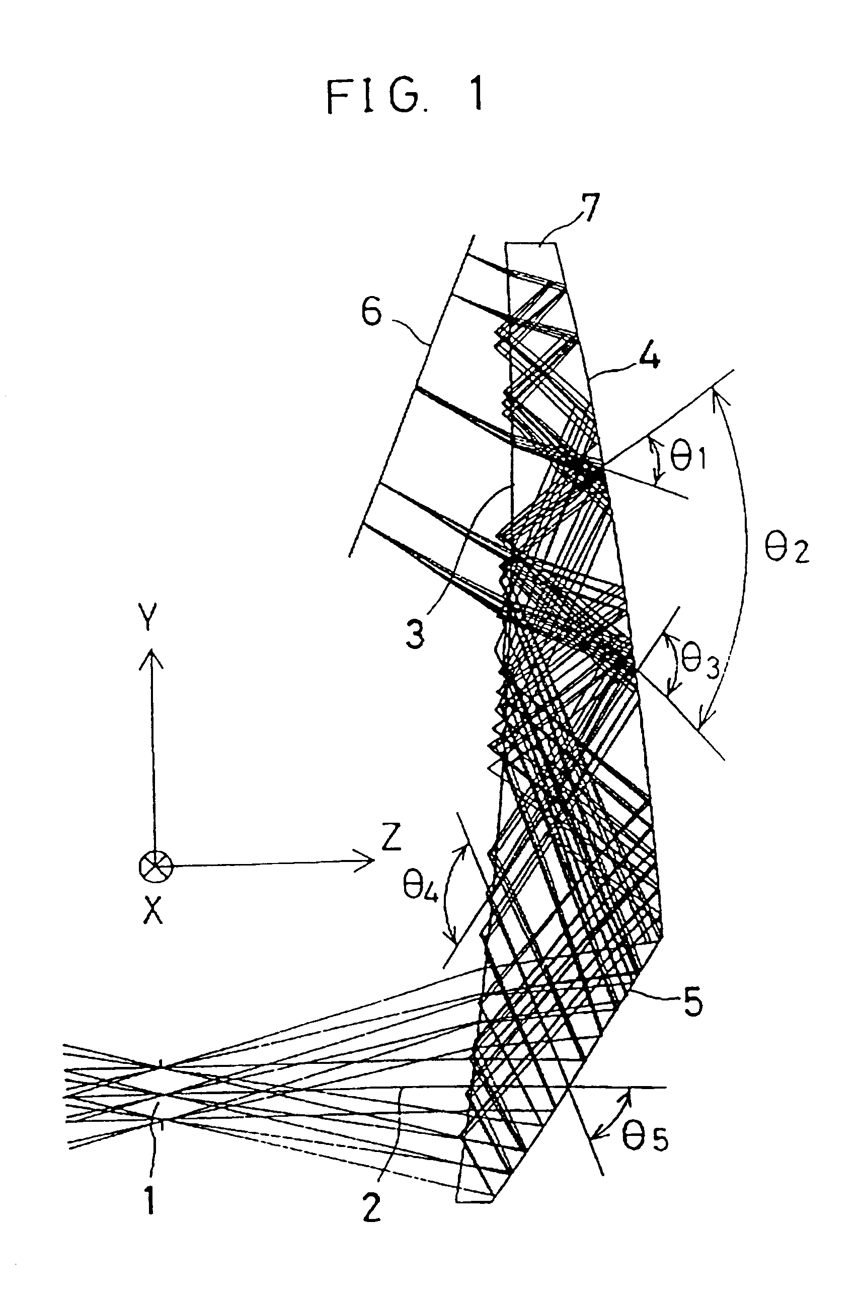
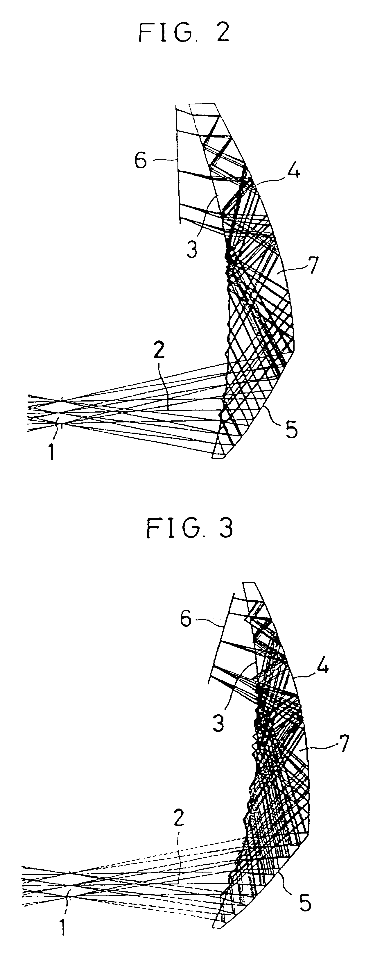
of the image display device constructed using the ocular optics system according to the present invention will now be explained with reference to the accompanying drawings.
Constitutional parameters of each example will now be given later. In what follows, surface numbers are given by back-tracing surfaces numbers as counted from an observer's pupil position 1 toward an image display element 6. As shown in FIG. 1, a coordinate system is composed of the origin defined by an observer's iris position 1, a Z axis defined by an observer's visual axis 2, whose direction from the origin toward an ocular optical system 7 is taken as being positive, a Y axis perpendicular to the observer's visual axis 2, whose direction from below to above with respect to an observer's eyeball is taken as being positive, and an X axis perpendicular to the observer's visual axis 2, whose direction from right to left with respect to the observer's eyeball is taken as being positive. In other words, a Y-Z plane is defined within a sheet plane of FIG. 1 while an X-Z plane is defined by a plane perpendicular to the sheet plane. An optical axis is here assumed to be turned back within the Y-Z plane on the sheet plane.
Of the constitutional parameters to be described later, Y, Z and .theta. represent amounts of decenteration of a vertex of a given surface from the reference surface (pupil position 1) in the Y and Z axis directions and an angle of inclination of a center axis of that given surface from the Z axis, respectively. Note that the plus sign attached to .theta. means the direction of counterclockwise rotation, and that the surface separation is of no significance.
For each surface, an irrotationally symmetric aspheric shape is given by
where, on the coordinates defining that surface, Ry and Rx are the paraxial radii of curvature of the aspheric surface within the Y-Z plane (sheet plane) and the X-Z plane, respectively, Kx and Ky are the conical coefficients of the aspheric surface within the X-Z plane and the Y-Z plane, respectively, AR and BR are the fourth- and sixth-order aspheric coefficients of the aspheric surface which is rotationally symmetric with respect to the Z axis, respectively, and AP and BP are the fourth- and sixth-order aspheric coefficients of the aspheric surface which is irrotationally symmetric with respect to the Z axis, respectively.
It is here to be noted that the refractive index of a medium between surfaces is given by a d-line refractive index, and that length is given in units of millimeters.
In the constitutional parameters to be described later, back-tracing is carried out from an object point position of a virtual image positioned 1-meter away from the pupil.

Example

FIGS. 1, 2 and 3 are sectional views of Examples 1, 2 and 3 of a monocular image display device. In these drawings, reference numeral 1 stands for an observer's pupil position, 7 an ocular optical system, 2 an observer's visual axis, 3 a first surface of the ocular optical system 7, 4 a second surface of the ocular optical system 7, 5 a third surface of the ocular optical system, and 6 an image display element.
Referring to actual optical paths in these examples, a pencil of light emanating from the image display element 6 is first incident on the ocular optical system 7 upon being refracted at the first surface 3 thereof, then is internally reflected at the second surface 4, the first surface 3, the second surface 4, the first surface 3 and the third surface 5 in the described order, then incident on the first surface 3 where it is refracted, and finally projected into an observer's eyeball while the iris position of the observer's pupil or the center of rotation of the observer's eyeball is taken as the exit pupil 1.
Horizontal and vertical field angles, and pupil diameter are 18.75.degree. and 25.degree., and 8 mm for Example 1; 22.5.degree. and 30.degree., and 4 mm for Example 2; and 30.degree. and 22.5.degree., and 4 mm for Example 3.
Throughout the examples, the surfaces are all anamorphic aspheric surfaces, and the first transmitting surface, second reflecting surface, fourth reflecting surface and second transmitting surface comprise the common first surface 3 while the first reflecting surface and third reflecting surface comprise the common second surface 4.
It should be noted that the ocular optical system of this invention is usable as an image optical system capable of forming an image of an object point at a distant place.
Enumerated below are the values of the constitutional parameters in Examples 1, 2 and 3. It is to be noted, however, that .theta..sub.1 to .theta..sub.5 represent angles which, as shown in FIG. 2, the principal ray--defined by a light ray leaving the center of the image display element 6 and arriving at the center of the pupil 1--incident on the first to fifth reflecting surfaces makes with the principal ray emerging therefrom.
EXAMPLE 1
Sur- face Sur- sep- Refractive face Radius of ar- index Abbe's No. No. curvature ation (Displacement) (Tilt angle) 1 .infin. (pupil) 2 R.sub.y -427.518 1.51633 64.1 R.sub.x -29.212 Y 17.473 .theta. -5.351.degree. K.sub.y 0 Z 26.387 K.sub.x 0 AR 0 BR 0 AP 0 BP 0 3 R.sub.y -254.887 1.51633 64.1 R.sub.x -649.767 Y 130.176 .theta. 12.443.degree. K.sub.y 0 Z 52.819 K.sub.x 0 AR -0.876797 .times. 10.sup.-6 BR 0 AP -0.713380 BP 0 4 R.sub.y -427.518 1.51633 64.1 R.sub.x -29.212 Y 17.473 .theta. -5.351.degree. K.sub.y 0 Z 26.387 K.sub.x 0 AR 0 BR 0 AP 0 BP 0 5 R.sub.y -242.504 1.51633 64.1 R.sub.x -42.527 Y -31.772 .theta. -8.869.degree. K.sub.y 0 Z 36.510 K.sub.x 0 AR 0 BR 0 AP 0 BP 0 6 R.sub.y -427.518 1.51633 64.1 R.sub.x -29.212 Y 17.473 .theta. -5.351.degree. K.sub.y 0 Z 26.387 K.sub.x 0 AR 0 BR 0 AP 0 BP 0 7 R.sub.y -242.504 1.51633 64.1 R.sub.x -42.527 Y -31.772 .theta. -8.869.degree. K.sub.y 0 Z 36.510 K.sub.x 0 AR 0 BR 0 AP 0 BP 0 8 R.sub.y -427.518 Y 17.473 .theta. -5.351.degree. R.sub.x -29.212 Z 26.387 K.sub.y 0 K.sub.x 0 AR 0 BR 0 AP 0 BP 0 9 (display device) Y 55.708 .theta. -22.615.degree. Z 21.266 .theta..sub.1 = 45.degree. .theta..sub.2 = 76.degree. .theta..sub.3 = 94.degree. .theta..sub.4 = 128.degree. .theta..sub.5 = 65.degree.

Example

EXAMPLE 2
Sur- face Refractive Sur- sep- index face Radius of ar- (Displace- Abbe's No. No. curvature ation ment) (Tilt angle) 1 .infin. (pupil) 2 R.sub.y -152.846 1.51633 64.1 R.sub.x -66.891 Y -13.768 .theta. -13.449.degree. K.sub.y 0 Z 27.500 K.sub.x 0 AR -0.178178 .times. 10.sup.-8 BR -0.594362 .times. 10.sup.-11 AP 0.105146 .times. 10 BP 0.664504 3 R.sub.y -119.363 1.51633 64.1 R.sub.x -82.534 Y 47.793 .theta. 6.177.degree. K.sub.y 0 Z 54.768 K.sub.x 0 AR -0.190871 .times. 10.sup.-6 BR 0.305496 .times. 10.sup.-11 AP 0.660695 .times. 10.sup.-1 BP 0.487236 4 R.sub.y -152.846 1.51633 64.1 R.sub.x -66.891 Y -13.768 .theta. -13.419.degree. K.sub.y 0 Z 27.500 K.sub.x 0 AR -0.178178 .times. 10.sup.-8 BR -0.594362 .times. 10.sup.-11 AP 0.105146 .times. 10 BP 0.664504 5 R.sub.y -118.626 1.51633 64.1 R.sub.x -82.339 Y -26.271 .theta. -14.237.degree. K.sub.y 0 Z 40.718 K.sub.x 0 AR -0.122336 .times. 10.sup.-7 BR -0.514035 .times. 10.sup.-12 AP -0.236341 .times. 10 BP 0.831265 6 R.sub.y -152.846 1.51633 64.1 R.sub.x -66.891 Y -13.768 .theta. -13.419.degree. K.sub.y 0 Z 27.500 K.sub.x 0 AR -0.178178 .times. 10.sup.-8 BR -0.594362 .times. 10.sup.-11 AP 0.105146 .times. 10 BP 0.664504 7 R.sub.y -118.626 1.51633 64.1 R.sub.x -82.339 Y -26.271 .theta. -14.237.degree. K.sub.y 0 Z 40.718 K.sub.x 0 AR -0.122336 .times. 10.sup.-7 BR -0.514035 .times. 10.sup.-12 AP -0.263241 .times. 10 BP 0.831265 8 R.sub.y -152.846 Y -13.768 .theta. -13.419.degree. R.sub.x -66.891 Z 27.500 K.sub.y 0 K.sub.x 0 AR -0.178178 .times. 10.sup.-8 BR -0.594362 .times. 10.sup.-11 AP 0.105146 .times. 10 BP 0.664504 9 (display device) Y 45.606 .theta. -1.625.degree. Z 22.237 .theta..sub.1 = 52.degree. .theta..sub.2 = 85.degree. .theta..sub.3 = 87.degree. .theta..sub.4 = 124.degree. .theta..sub.5 = 66.degree.

PUM

no PUM

Description & Claims & Application Information

We can also present the details of the Description, Claims and Application information to help users get a comprehensive understanding of the technical details of the patent, such as background art, summary of invention, brief description of drawings, description of embodiments, and other original content. On the other hand, users can also determine the specific scope of protection of the technology through the list of claims; as well as understand the changes in the life cycle of the technology with the presentation of the patent timeline. Login to view more.

Similar technology patents

Imaging lens

Owner:TOKYO VISIONARY OPTICS CO LTD

Optical system, image capturing module and terminal

ActiveCN114839748AImprove yieldAberration correctionOptical elementsOphthalmologyImage capture
Owner:JIANGXI JINGCHAO OPTICAL CO LTD

Optical lens for long-distance shooting

PendingCN114815174ALarge field of viewAberration correctionOptical elementsPhysicsLong-focus lens
Owner:东莞晶彩光学有限公司

Imaging lens

Owner:TOKYO VISIONARY OPTICS CO LTD

Classification and recommendation of technical efficacy words

  • Aberration correction
  • Light weight

Imaging lens

ActiveUS20120162769A1Small powerAberration correctionDiffraction gratingsImage resolutionLarge aperture
Owner:TOKYO VISIONARY OPTICS CO LTD

Optical apparatus

InactiveUS20080130128A1Aberration correctionSmall and low-costLensWhole systemsBrightness perception
Owner:ALPS ALPINE CO LTD

Dual-focus switchable lens

InactiveUS20070070523A1High densityAberration correctionLensPhysicsDual focus
Owner:FUJI PHOTO OPTICAL CO LTD

Projection lens system

InactiveUS6912095B2Aberration correctionExhibit optical stabilityPhotographic printingCamera body detailsDistortionPhysics
Owner:TAMRON

People also interested in

Why Eureka
Try Eureka