Unidirectional panel

a technology of unidirectional panels and panels, applied in the field of panels, can solve the problems of reducing the intensity of light of the image, affecting the visibility of the panel from the other side to the other side, and affecting the effect of the imag

Inactive Publication Date: 2001-05-22
CONTRA VISION
View PDF49 Cites 114 Cited by
  • Summary
  • Abstract
  • Description
  • Claims
  • Application Information

AI Technical Summary

Benefits of technology

A simple unidirectional vision panel comprises an opaque pattern of dots 1 mm in diameter and at a distance of 1.4 mm between the centers of adjacent dots on a square grid appearing white from one side and black from the other side, the other side being less illuminated than the one side. Light incident on the white dots is reflected and scattered, which has the effect of obscuring visibility from the one side into the other side. However, a substantially clear view is obtained from the other side .[.throught.]. .Iadd.through .Iaddend.the panel into the one side, albeit the intensity of light of the image is reduced by virtue of the degree of opacity, giving a "toned down" effect to the image, not dissimilar to tinted transparent panels.

Problems solved by technology

Vision from either side can be totally obstructed.
In another example, visibility through the panel from one side to the other side is totally or partially obstructed and visibility through the panel from the other side to the one side is totally or partially obstructed.

Method used


Image

  • Unidirectional panel
  • Unidirectional panel
  • Unidirectional panel

Examples


Embodiment Construction

In the various embodiments, like parts have been given the same reference numerals.

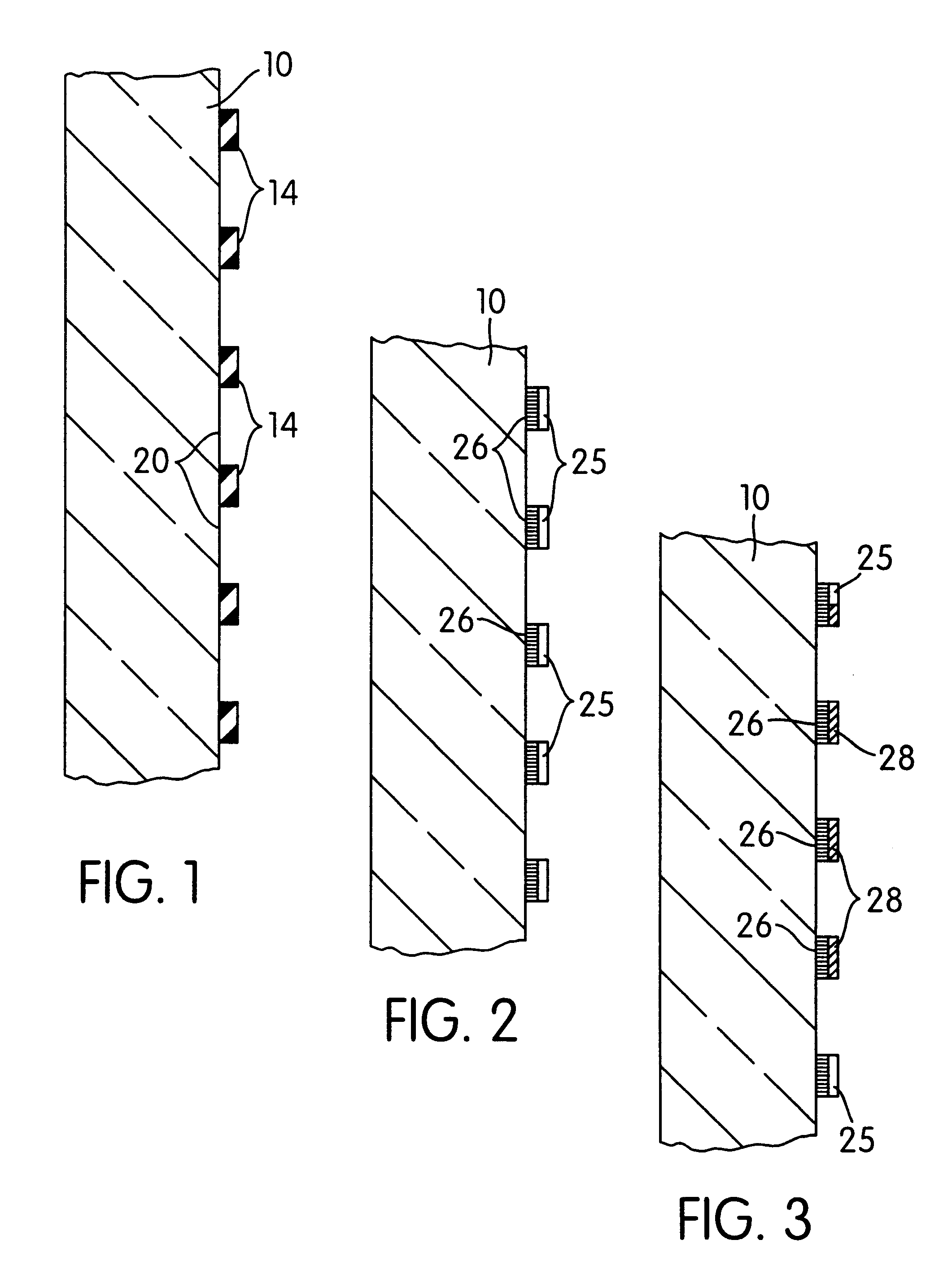
Referring to FIG. 1, the panel therein illustrated comprises a transparent colorless sheet of material 10 having a regular pattern of opaque ink 14 applied to one side thereof.

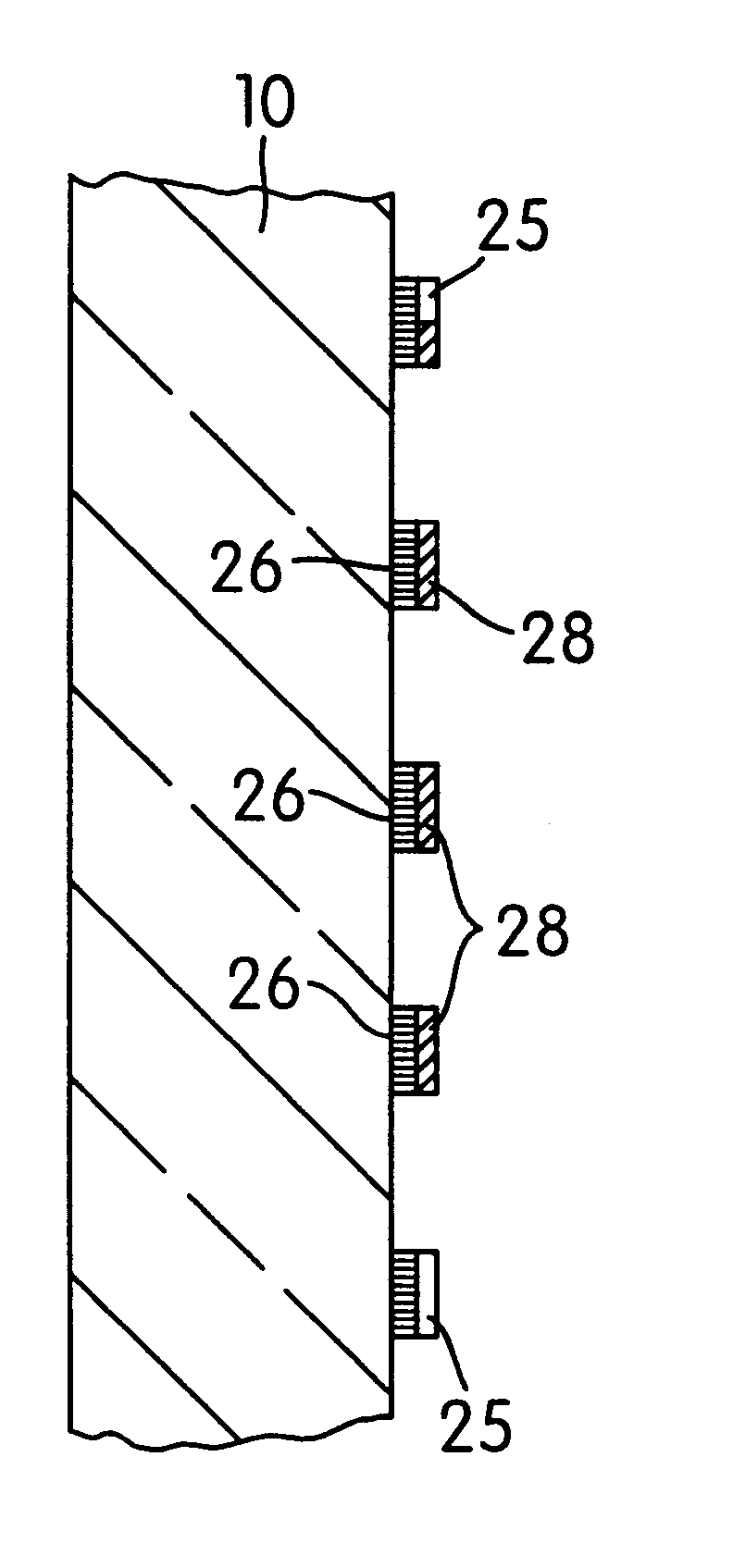
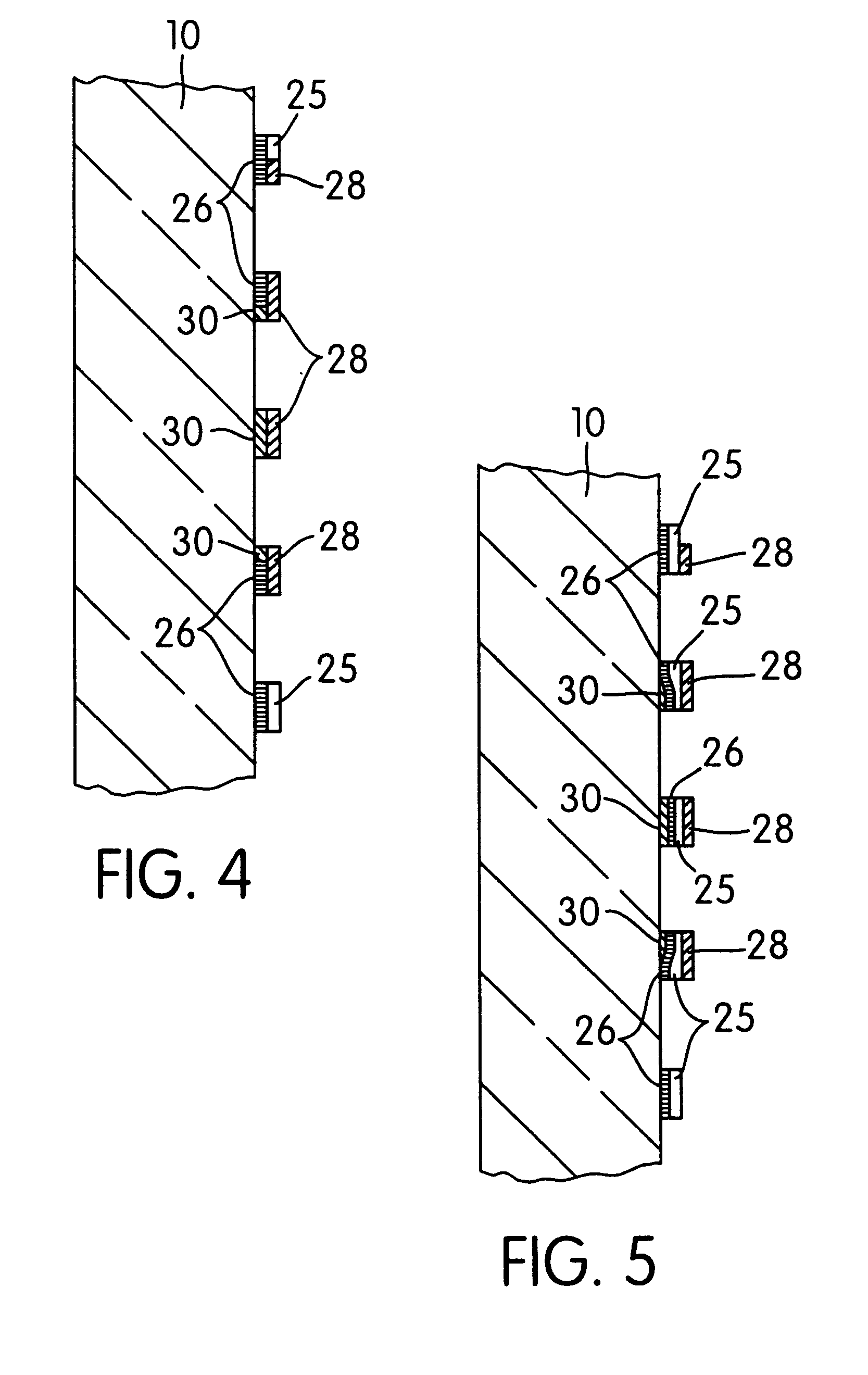
The panel of FIG. 2 has a regular pattern of dark ink 26 on one side of the sheet 10 and is superimposed by light colored or light reflective ink 25. When viewed from the front (that is from the right as illustrated in FIG. 2) the light colored pattern 25 has the effect of inhibiting vision through the panel. From the other side, however, the less reflective dark colored pattern 26 does not prevent vision through the panel. This one way effect is further enhanced if the level of illumination on the front of the panel is greater than at the rear.

The panel of FIG. 3 is similar to that of FIG. 2 except that part of the light colored ink pattern 25 is replaced with ink which is of a different color 28. The relative arrangement of th...


PUM

PropertyMeasurementUnit
diameteraaaaaaaaaa
diameteraaaaaaaaaa
areaaaaaaaaaaa

Abstract

A panel which comprises a substrate of transparent or translucent material having applied to one or both sides a design superimposed on, or forming part of, an opaque pattern so that the design on one side of the panel cannot be seen from the other side. This is a Reissue of a Patent which was the subject of a Reexamination Certificate No. B1 4,673,609, dated Jul. 25, 1995, Request No. 90/003,201, Sep. 21, 1993.

Description

FIELD OF THE INVENTIONThis invention relates to panels and more particularly transparent or translucent panels having a design or pattern visible from at least one side and not the other.BACKGROUND OF THE INVENTIONThe term transparent panel as used herein includes a sheet of transparent material, a laminate of transparent materials or an assembly of transparent materials, such as glass or plastics, for example, acrylic sheets or polycarbonate sheets and including flexible materials such a polyester film or polyvinyl chloride film and also includes a transparent panel having an obscure or other distorted image effect. Similarly, the term translucent panel is intended to include a sheet of translucent material, a laminate of translucent materials such as glass or plastics, for example, acrylic sheets or polycarbonate sheets and including flexible materials such as polyester film, polyvinyl chloride film, paper, fabric or other material.The incorporation of an opaque pattern on or into...

Claims


Application Information

Patent Timeline
Patent Type & Authority Patents(United States)
IPC IPC(8): B32B17/10B32B17/06B44F1/00B44F1/06B44C3/00B44C5/00B44C1/00B44C1/17B44C3/02B44C1/10B44C5/04B44F1/10B41M3/00E06B9/24F21V9/00G02B5/00G09F7/00G09F13/00
CPCB32B17/10247B44C1/17B44C3/005B44C3/02B44C5/04B44C5/0446B44F1/06B44F1/10G09F7/00G09F13/00B44C1/105Y10T428/24298E06B9/24Y10T428/24306Y10T428/24603Y10T428/24769Y10T428/24736Y10T428/24876Y10T428/24909Y10T428/24322Y10T428/24314Y10T428/24331Y10T428/24058Y10T428/24281Y10T428/24289
Inventor HILL, GEORGE ROLAND
Owner CONTRA VISION
Why Eureka
Try Eureka