Polarization viewer

a viewer and component technology, applied in the field of polarization viewers, can solve the problems of inability to obtain polarization component images, complicated or possibly infeasible,

Inactive Publication Date: 2002-06-18
EQUINOX CORP
View PDF22 Cites 37 Cited by
  • Summary
  • Abstract
  • Description
  • Claims
  • Application Information

AI Technical Summary

Benefits of technology

In a first embodiment, the providing mechanism or means includes a camera mechanism or means in communication with the forming mechanism or means. The camera mechanism or means includes a fixed polarizer analyzer disposed such that electromagnetic radiation entering the camera mechanism or means passes through the polarizer analyzer. The providing mechanism or means can also include a mechanism or means for steering a polarization plane of the radiation. The steering mechanism or means is disposed such that radiation passing through the polarizer analyzer first passes through the steering mechanism or means. The steering mechanism or means preferably includes a first twist crystal in a first embodiment and at least a second twist crystal aligned with the first twist crystal such that radiation passing through the first crystal then passes through the second crystal in a second embodiment. Each crystal has a first state and a second state. The first state does not effect the polarization plane of the radiation as the radiation passes through the crystal. The second state rotates the polarization plane of the radiation as the radiation passes through the crystal.

Problems solved by technology

. . ) which are more complicated or possibly infeasible when limited to using intensity and color information.
A criticism that has sometimes been leveled at polarization-based vision methods is the inconvenience of obtaining polarization component images by having to place a linear polarizing filter in front of an intensity CCD camera and mechanically rotating this filter by hand or by motor into different orientations.
This inconvenience is a result of commercially available camera sensors being geared towards taking intensity images instead of polarization images.

Method used


Image

  • Polarization viewer
  • Polarization viewer
  • Polarization viewer

Examples


Embodiment Construction

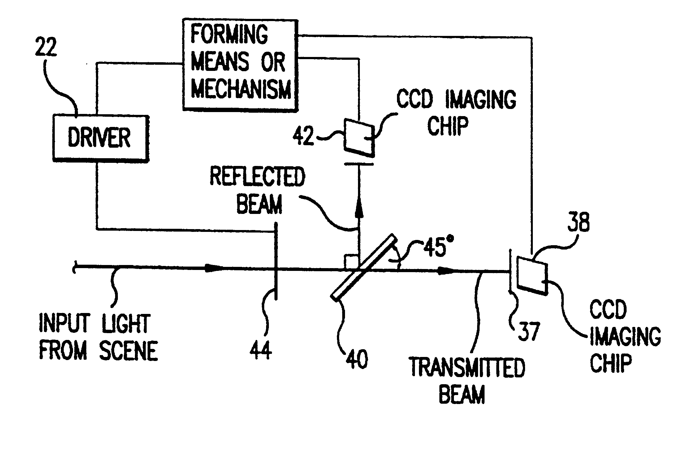
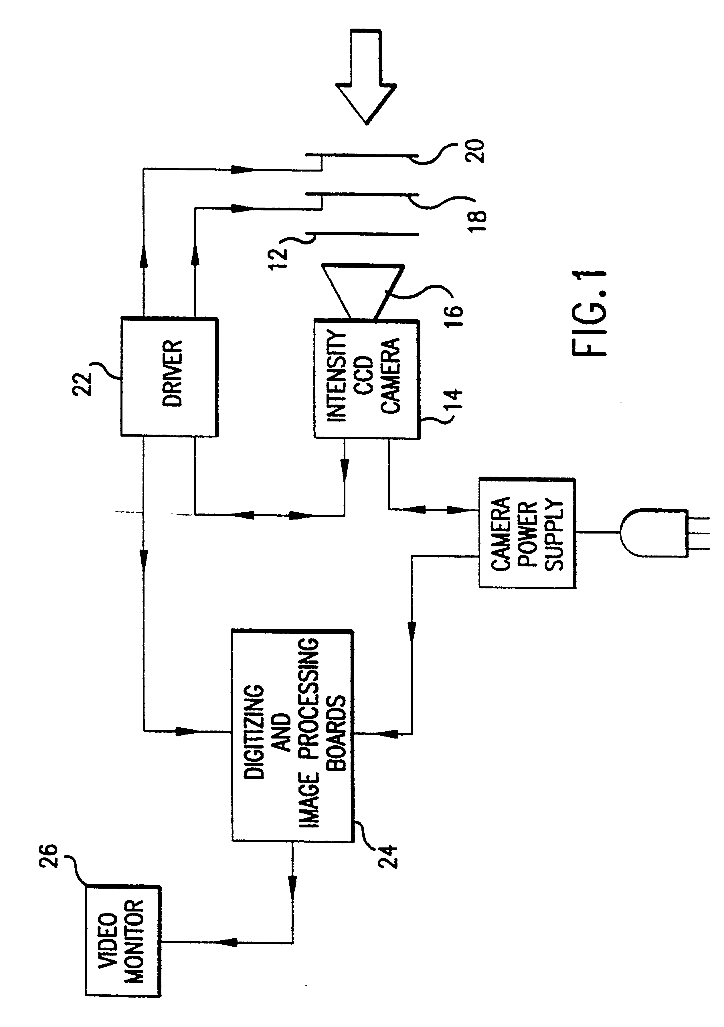
Referring now to the drawings wherein like reference numerals refer to similar or identical parts throughout the several views, and more specifically to FIG. 1 thereof, there is shown a polarization viewer 10. The polarization viewer 10 is comprised of a mechanism or means for forming a broadview image having a spectral width preferably greater than 2 angstroms and 0.50.degree. based on polarization information of a scene, although it can be used within this range. Preferably, the spectral width is between 100-11,000 nanometers and at least 380-800 nanometers, while the angle can be .+-.20.degree.. The viewer 10 is also comprised of a mechanism or means for providing polarization information to the forming mechanism or means. The providing mechanism or means preferably includes a camera mechanism or camera means in communication with the forming mechanism or means. The camera mechanism or camera means preferably includes a fixed polarizer analyzer 12 disposed such that electromagnet...


PUM


Abstract

A polarization viewer comprising a mechanism for forming a broadview image having a spectral width greater than 2 angstroms and 0.50° based on polarization information of a scene. The polarization viewer is also comprised of a mechanism for providing polarization information to the forming mechanism. The providing mechanism is in communication with the forming mechanism. In a first embodiment, the providing mechanism includes a camera mechanism in communication with the forming mechanism. The camera mechanism includes a fixed polarizer analyzer disposed such that electromagnetic radiation entering the camera mechanism passes through the polarizer analyzer. The providing mechanism can also include a mechanism for steering a polarization plane of the radiation. The steering mechanism is disposed such that radiation passing through the polarizer analyzer first passes through the steering mechanism. The steering mechanism preferably includes a first twist crystal and at least a second twist crystal aligned with the first twist crystal such that radiation passing through the first crystal then passes through the second crystal. Each crystal has a first state and a second state. The first state does not effect the polarization plane of the radiation as the radiation passes through the crystal. The second state rotates the polarization plane of the radiation as the radiation passes through the crystal.

Description

FIELD OF THE INVENTIONThe present invention is related to polarization viewers. More specifically, the present invention is related to a polarization viewer that preferably forms a transmitted radiance sinusoid in order to form an image based on polarization information concerning a scene.BACKGROUND OF THE INVENTIONIn the context of physics-based vision there is in fact a compelling motivation to study polarization vision-polarization affords a more general description of light than does intensity, and can therefore provide a richer set of descriptive physical constraints for the interpretation of an imaged scene. As intensity is the linear sum of polarization components, intensity images physically represent reduced polarization information. Because the study of polarization vision is more general than intensity vision, there are polarization cues that can immensely simplify some important visual tasks (e.g., region and edge segmentation, material classification, etc. . . ) which a...

Claims


Application Information

Patent Timeline
Patent Type & Authority Patents(United States)
IPC IPC(8): G01J4/00G01J4/04
CPCG01J4/04
Inventor WOLFF, LAWRENCE B.
Owner EQUINOX CORP
Why Eureka
Try Eureka