Method for scanning microscopy; and scanning microscope

Inactive Publication Date: 2005-10-25
LEICA MICROSYSTEMS CMS GMBH
View PDF36 Cites 31 Cited by
  • Summary
  • Abstract
  • Description
  • Claims
  • Application Information

AI Technical Summary

Benefits of technology

[0014]It is therefore the object of the invention to describe a method for scanning microscopy that make

Problems solved by technology

Arrangements having fixed color filters or dichroic filters do not offer sufficient universality, and are complex and cumbersome in terms of handling.
Arrangements having acoustooptical components offer a flexible selection onl

Method used


Image

  • Method for scanning microscopy; and scanning microscope
  • Method for scanning microscopy; and scanning microscope
  • Method for scanning microscopy; and scanning microscope

Examples


Embodiment Construction

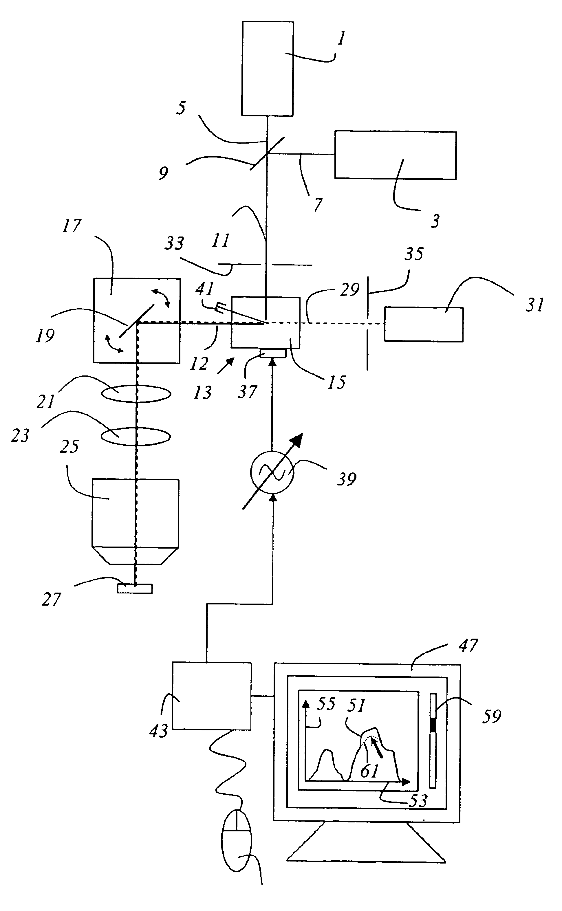
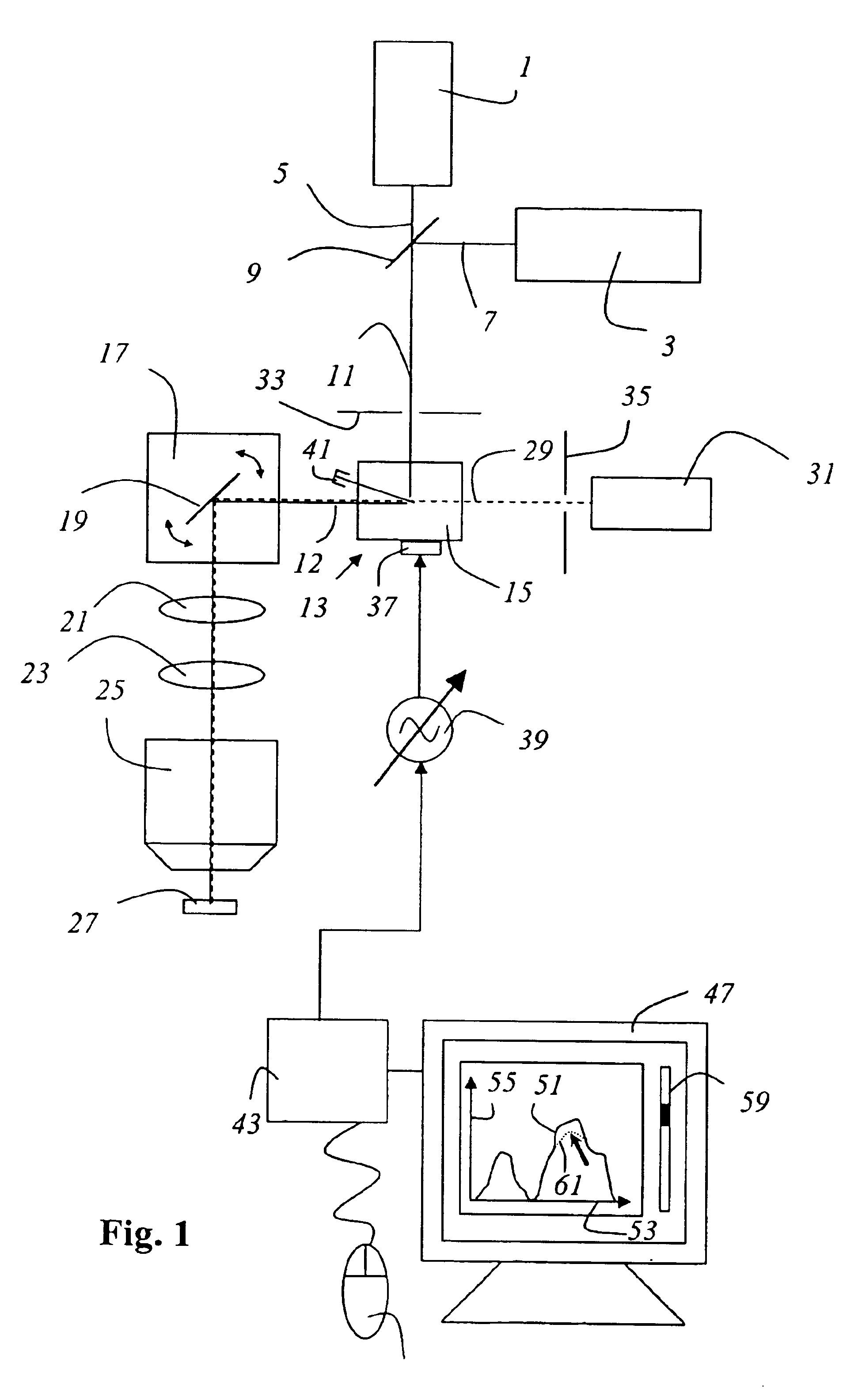
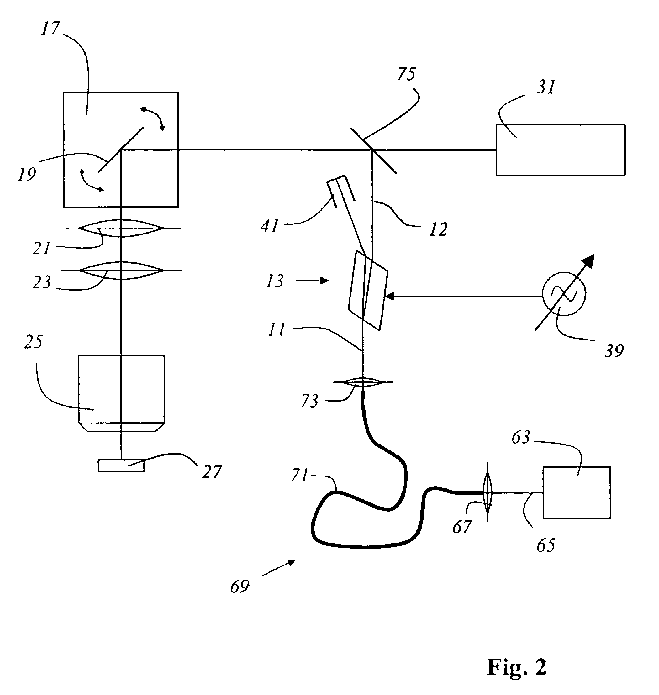
[0034]FIG. 1 shows a scanning microscope according to the present invention that is embodied as a confocal scanning microscope, having two lasers 1, 3 whose emitted light beams 5, 7, which are of different wavelengths, are combined with dicbroic beam combiner 9 into one illuminating light beam 11. The scanning microscope comprises an acoustooptical component 13 that is embodied as AOTF 15. From acoustooptical component 13, light 12, selected out of illuminating light beam 11, arrives at a beam deflection device 17 that contains a gimbal-mounted scanning mirror 19 and that guides illuminating light beam 11 through scanning optical system 21, tube optical system 23, and objective 25 over or through specimen 27. Detected light beam 29 coming from the specimen travels in the opposite direction through scanning optical system 21, tube optical system 23, and objective 25, and arrives via scanning mirror 19 at acoustooptical component 13 which conveys detected light beam 29 to detector 31,...


PUM


Abstract

A method for scanning microscopy is disclosed. It contains the step of generating an illuminating light beam that exhibits at least a first substantially continuous wavelength spectrum whose spectral width is greater than 5 nm; the choosing of a second wavelength spectrum that is arranged spectrally within the first wavelength spectrum; the step of selecting the light of the second wavelength spectrum out of the illuminating light beam using an acoustooptical component; and the step of illuminating a specimen with the illuminating light beam. A scanning microscope is also disclosed.

Description

CROSS REFERENCE TO RELATED APPLICATIONS[0001]This application claims priority of the German patent application 101 37 158.6 which is incorporated by reference herein.FIELD OF THE INVENTION[0002]The invention concerns a method for scanning microscopy. The invention furthermore concerns a scanning microscope and a confocal scanning microscopeBACKGROUND OF THE INVENTION[0003]In scanning microscopy, a specimen is illuminated with a light beam in order to observe the detected light, constituting reflected or fluorescent light, emitted by the specimen. The focus of an illuminating light beam is moved in a specimen plane by means of a controllable beam deflection device, generally by tilting two mirrors; the deflection axes are usually perpendicular to one another, so that one mirror deflects in the X direction and the other in the Y direction. Tilting of the mirrors is brought about, for example, by means of galvanometer positioning elements. The power level of the detected light coming f...

Claims


Application Information

Patent Timeline
IPC IPC(8): G02B21/00G02B21/06
CPCG02B21/002G02B21/06
Inventor ENGELHARDT, JOHANNHOFFMANN, JUERGEN
Owner LEICA MICROSYSTEMS CMS GMBH
Why Eureka
Try Eureka