Pressurized water closet flushing system

a pressurized water closet and flushing technology, applied in the field of pressurized water closets, can solve the problems of relatively inefficient propulsion energy that affects the waste extraction of the toilet bowl, and achieve the effect of improving the waste extraction energy and improving the consistency and reliability of the flushing action

Inactive Publication Date: 2002-12-10
GEBERIT AG
View PDF29 Cites 23 Cited by
  • Summary
  • Abstract
  • Description
  • Claims
  • Application Information

AI Technical Summary

Benefits of technology

The pressurized water closet flushing system of the present invention solves the aforesaid problems. Specifically, the system exhibits a substantial improvement in waste extraction energy and in the consistency and reliability of the flushing action. The system uses a minimum volume of water upon discharge; provides internal pressure relief upon the occurrence of water system pressure above design pressure; has a flush action that is not a function of time of actuator depression; exhibits positive closure upon the occurrence of low supply line pressure; has a self cleaning actuator valve; and toilet bowl refill volume can be customized to meet application specifications. Moreover, the system exhibits minimal differences in water consumption at high and low water pressures; utilizes two internal back checks, a built in drain, an internal discharge port, and provides for the addition of disinfectant to the toilet bowl without compromise of flushing system integrity.

Problems solved by technology

Specifically, propulsion energy that effects waste extraction from the toilet bowl is relatively inefficient; high or low pressure in the fresh water system may result in inconsistent operation; the volume of water discharged is inconsistent; there is no provision for internal release of water system pressure above design pressure; flush action is not independent of duration of flush valve actuator depression; closure of the flush valve upon the occurrence of low supply line pressure is not positive; the actuator valve is not self cleaning; there is no provision for varying toilet bowl refill volume, and there is no provision for the addition of disinfectant to the toilet bowl without compromise of flushing system integrity.

Method used


Image

  • Pressurized water closet flushing system
  • Pressurized water closet flushing system
  • Pressurized water closet flushing system

Examples


Embodiment Construction

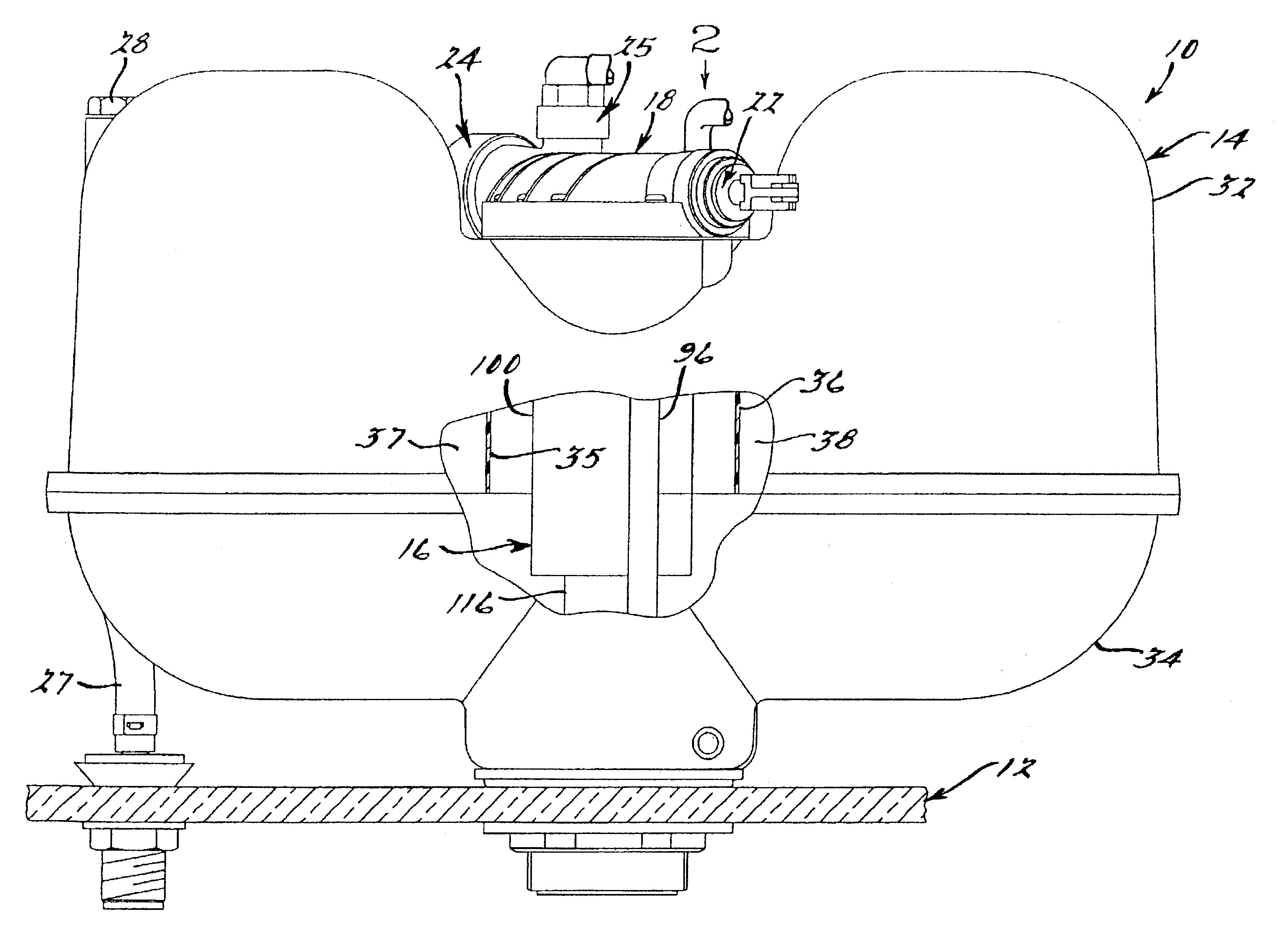
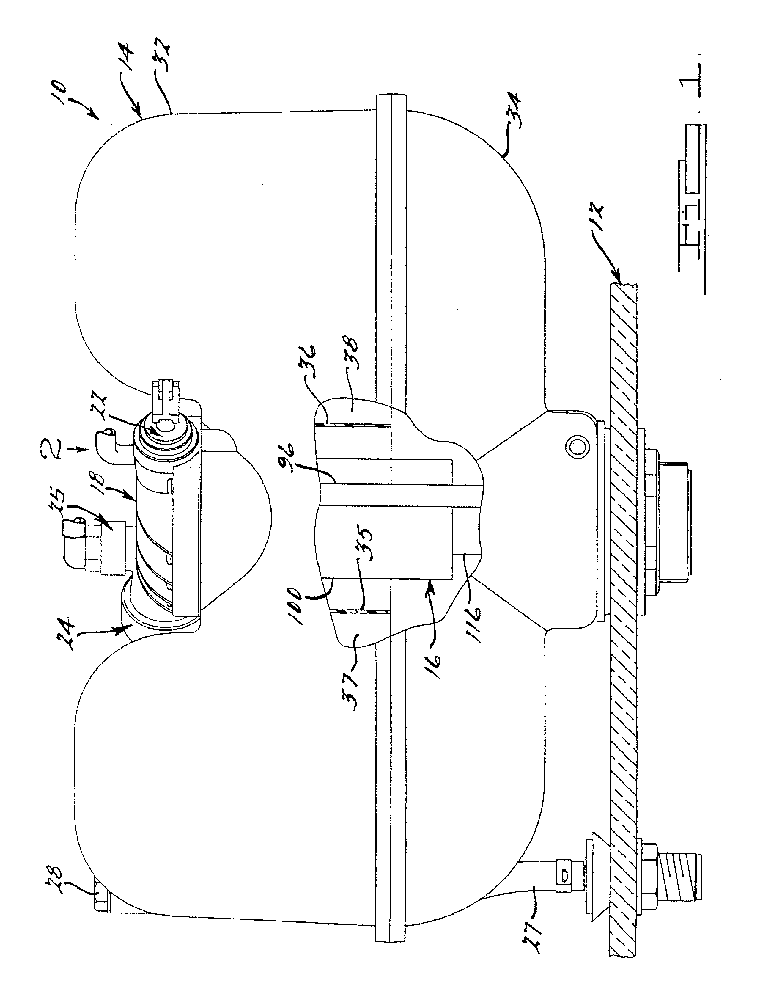
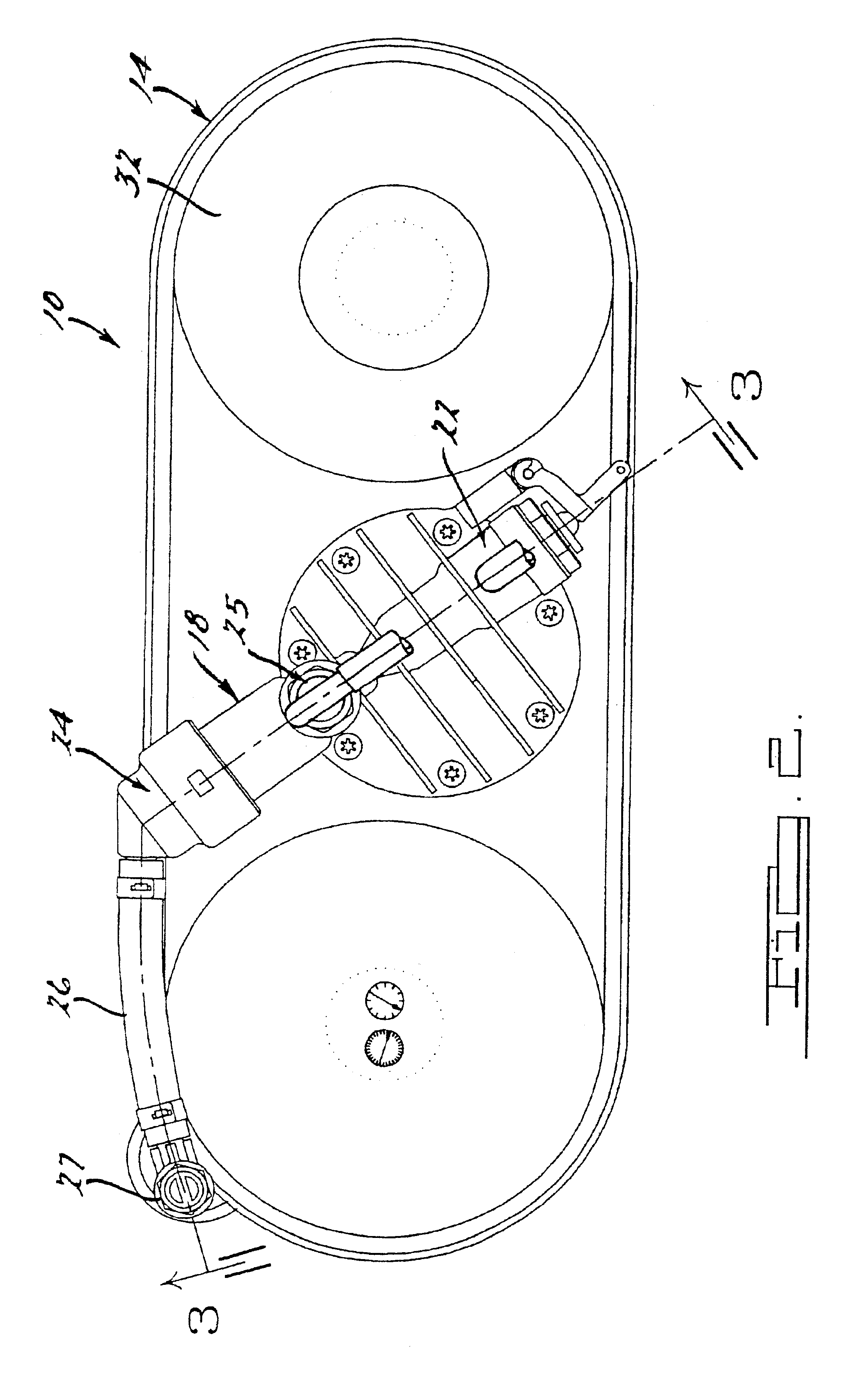
As seen in FIGS. 1 and 2, a pressurized water closet flushing system 10, in accordance with a preferred and constructed embodiment of the present invention, is shown in operative association with a conventional water closet tank 12. Major components of the system 10 are a water vessel 14, an internal flush valve assembly 16, and a manifold 18 comprising an integral flush valve actuator 22, a water pressure regulator 24, an air induction regulator 25 as seen in FIG. 3, a disinfectant reservoir 26.

Water is supplied to the system 10 from a pressurized source (not shown) and flows upwardly without restriction through an inlet conduit 27 and vacuum breaker 28, thence laterally to the manifold 18. Water is free to flow through the conduit 27 to the manifold 18 at system pressure thence, after regulation, to both the flush valve assembly 16 and water vessel 14, as will be described.

The size of the water vessel 14 is dictated by energy requirements of the system 10. In the preferred constru...


PUM


Abstract

A pressurized water closet operating system comprises a water vessel, an external manifold mounted directly on said vessel, and an internally mounted flush valve assembly. The manifold comprises a water pressure regulator, an air induction system, and a manually operable flush valve actuator. The manually operable flush valve actuator controls the discharge of water under pressure from the water vessel into the toilet bowl.

Description

BACKGROUND OF THE INVENTION1. Field of the InventionThe present invention relates to an improved pressurized water closet that minimizes water usage incident to flushing yet maximizes waste extraction propulsion energy and reliability of the system.2. Related ArtThe herein disclosed pressurized water closet is an improvement over the systems disclosed in U.S. Pat. No. 4,233,698 issued Nov. 18, 1980 and U.S. Pat. No. 5,361,426 issued Nov. 8, 1994, as well as over the system disclosed in application Ser. No. 08 / 457,162 filed Jun. 1, 1995.The basic components of a pressurized water closet are a water vessel, a flush valve and a flush valve actuator. The aforesaid components are generally installed internally of a conventional water closet. The pressurized water closet is energized by water pressure from a conventional fresh water supply system.In operation, as the water level rises in the water vessel after flush, air internally of the water vessel is compressed. When water pressure in...

Claims


Application Information

Patent Timeline
Patent Type & Authority Patents(United States)
IPC IPC(8): E03D3/10E03D3/00
CPCE03D3/10
Inventor MARTIN, RAYMOND BRUCEBEH, THOMAS P.MROCCA, MARK M.
Owner GEBERIT AG
Why Eureka
Try Eureka