Embeddable mounting device and method

Inactive Publication Date: 2003-02-11
GREGORY HLDG L L C
View PDF30 Cites 10 Cited by
  • Summary
  • Abstract
  • Description
  • Claims
  • Application Information

AI Technical Summary

Problems solved by technology

In addition, because the concrete block is harder than the cement/grout it is more difficult to dig ou

Method used


Image

  • Embeddable mounting device and method
  • Embeddable mounting device and method
  • Embeddable mounting device and method

Examples


Embodiment Construction

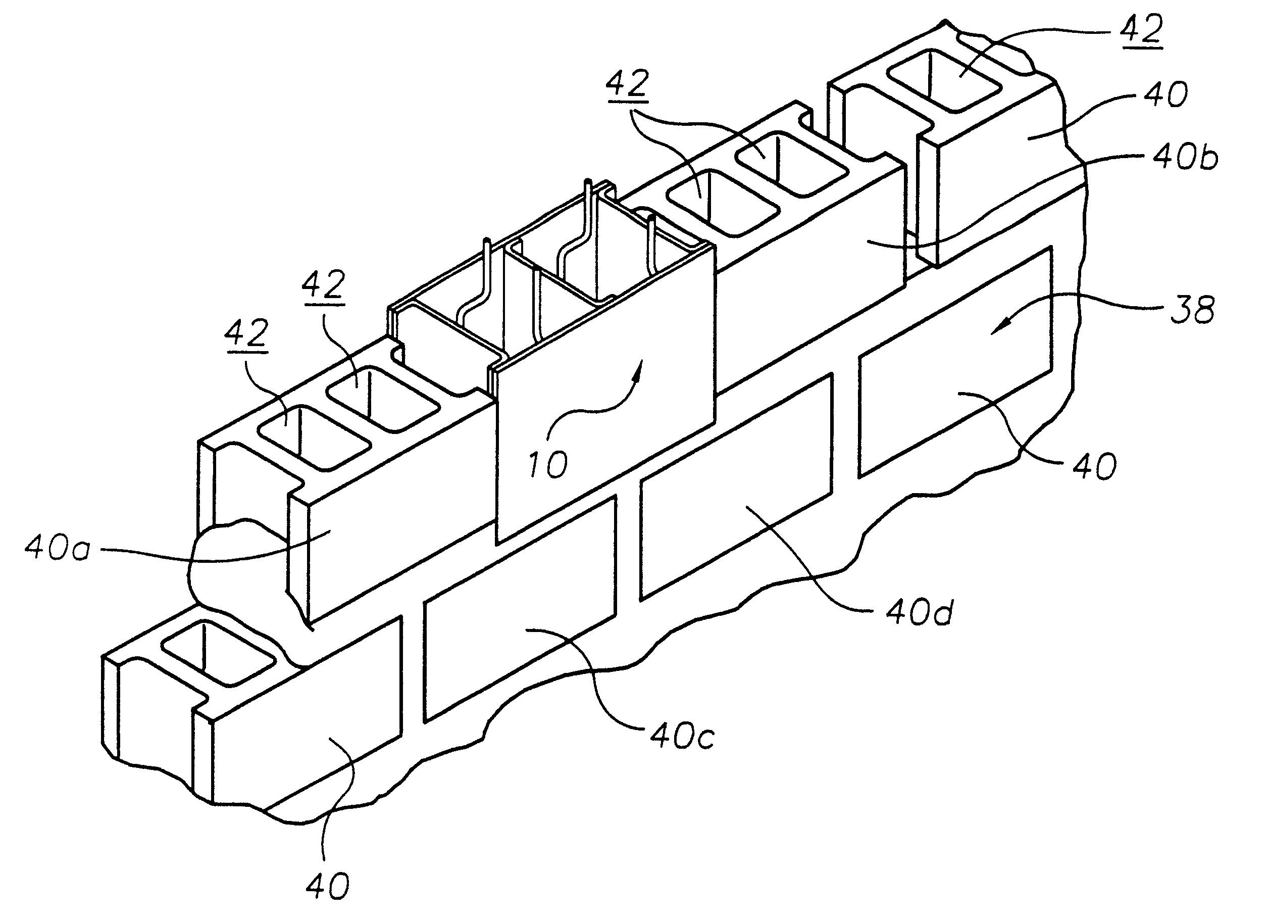
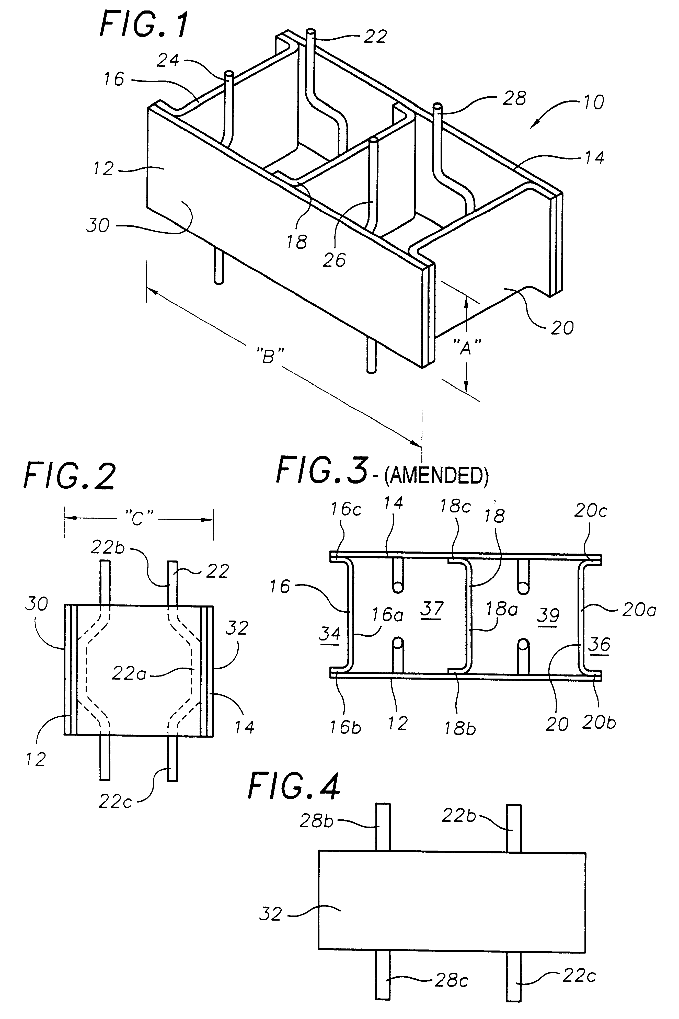
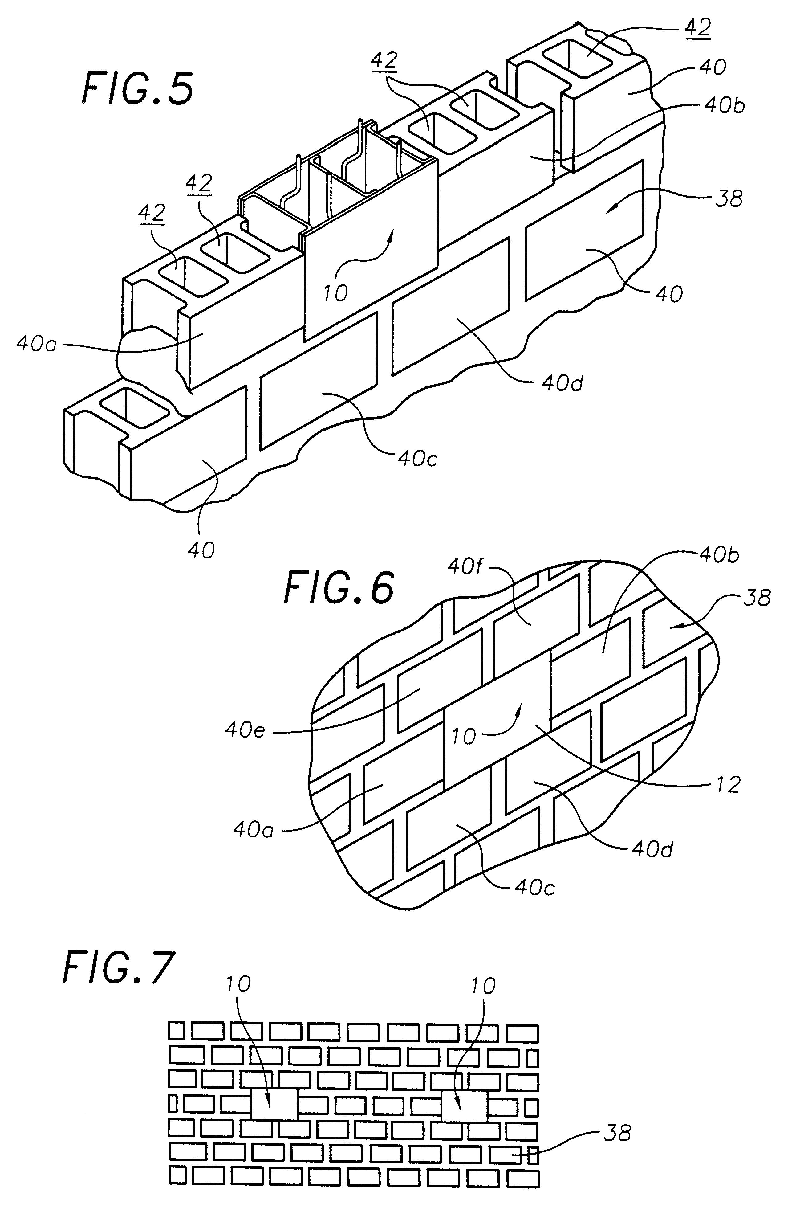
FIG. 1 is a perspective view of an exemplary embodiment of the embeddable mounting device of the present invention generally designated by the numeral 10. Mounting device 10 includes a first rectangular metal plate member 12; a second rectangular metal plate member 14; first, second and third vertical spacer members 16,18,20; and four vertical reinforcing bars 22,24,26,28. In this embodiment first and second metal plate members 12,14 are both one-quarter (1 / 4") inch thick mild steel plates having a height "A" of eight and five-eighths (85 / 8") inches and a width "B" of sixteen and three-quarters 163 / 4") inches. With reference to FIG. 2, first and second plate members 12,14 are secured together and spaced a distance "C", between an outwardly facing first outer surface 30 (more clearly shown in FIG. 1) and outwardly facing second outer surface 32 (more clearly shown in FIG. 4), a distance of seven and five-eights (75 / 8") inches, by the three vertical spacer members 16,18,20 (FIG. 3). E...


PUM


Abstract

A embeddable mounting device and method for permanently affixing a fixture to a concrete block wall. The embeddable mounting device comprises a first rectangular metal plate member; a second rectangular metal plate member having dimensions equal to the first metal plate; and a pair of vertical spacer members secured between the first inner surface and the second inner surface in a manner to create at least one reinforcing bar and cement receiving cavity between the first and second metal plate members, and in a manner to hold the first and second metal plate members in parallel relationship with each other such that when said first and second metal plate members simultaneously contact a planar surface the first and second metal plate members are both perpendicularly oriented to the planar surface. A method of installing a fixture utilizing the mounting device is also described.

Description

TECHNICAL FIELDThe present invention relates to devices and methods utilized to permanently install fixtures, such as a steel wall plates, a shelves, beds, cabinets, etc., to a wall in a security facility, such as a jail, prison, juvenile detention center, or psychiatric hospital, and more particularly to an embedable wall construction unit installable within a wall in a manner to have at least one surface exposed to the surface of the wall that is suitable for forming a permanent attachment with fixtures, such as steel wall plates, beds, shelves, cabinets, etc., to anchor the fixture permanently in place, and a method of utilizing the embedable wall construction unit for permanently securing fixtures to a concrete block wall.BACKGROUND ARTIt is a common practice within the detention industry and other public facilities, such as jails, prisons, juvenile detention centers, and psychiatric hospitals, to permanently affix certain furnishing such as the beds, cabinets, shelves, lavatori...

Claims


Application Information

Patent Timeline
IPC IPC(8): E04B1/41E04H3/08
CPCE04B1/41E04H3/08
Inventor LAYNE, HARRY R.
Owner GREGORY HLDG L L C
Why Eureka
Try Eureka