Ceiling fan outlet box

a ceiling fan and outlet box technology, applied in the field of ceiling boxes, can solve the problems of not providing sufficient strength, requiring additional mounting means for proper support, and ears that cannot be threaded through holes, and achieve the effect of superior structur

Inactive Publication Date: 2003-05-20
THOMAS & BETTS INT INC
View PDF47 Cites 16 Cited by
  • Summary
  • Abstract
  • Description
  • Claims
  • Application Information

AI Technical Summary

Benefits of technology

A still further object is to provide a ceiling box which is structurally superior and allows installation of a ceiling fan in a conventional manner.

Problems solved by technology

For ceiling fans, conventional ceiling boxes do not provide sufficient strength to serve as support structures, thus requiring additional mounting means for proper support.
In the Jorgensen box, however, the ears are unthreaded through holes, aligned with threaded mounting holes formed in the top portion of the box.
Also, it is frequently difficult to thread the screws into the mounting holes since the holes, being recessed within the box, are hard to see, especially when a ceiling fan mounting plate blocks the installer's view.

Method used


Image

  • Ceiling fan outlet box
  • Ceiling fan outlet box
  • Ceiling fan outlet box

Examples


Embodiment Construction

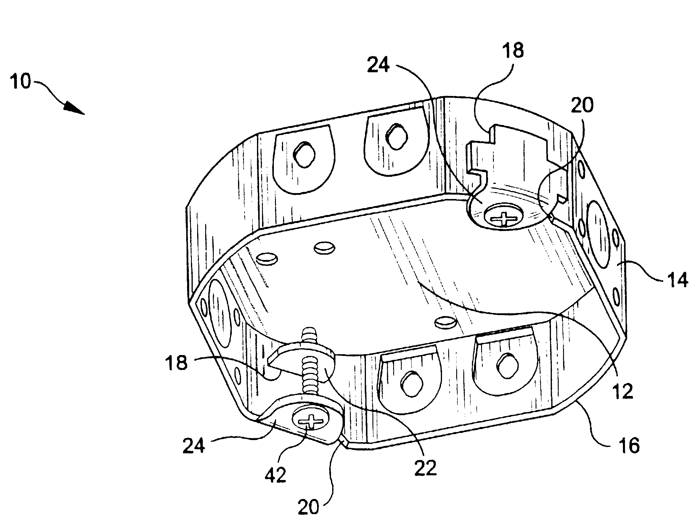
Referring initially to FIG. 1, an electrical ceiling box 10 is shown, comprising a top portion 12 peripherally bounded by side portion 14. Top portion 12 and side portion 14 may be formed from separate pieces of metal and rigidly secured to one another, as by welding, or they may be contiguous components of a single piece of metal formed by stamping or any other suitable process. As with conventional ceiling boxes, box 10 has an open end defined by edge 16, which faces downward upon normal installation.

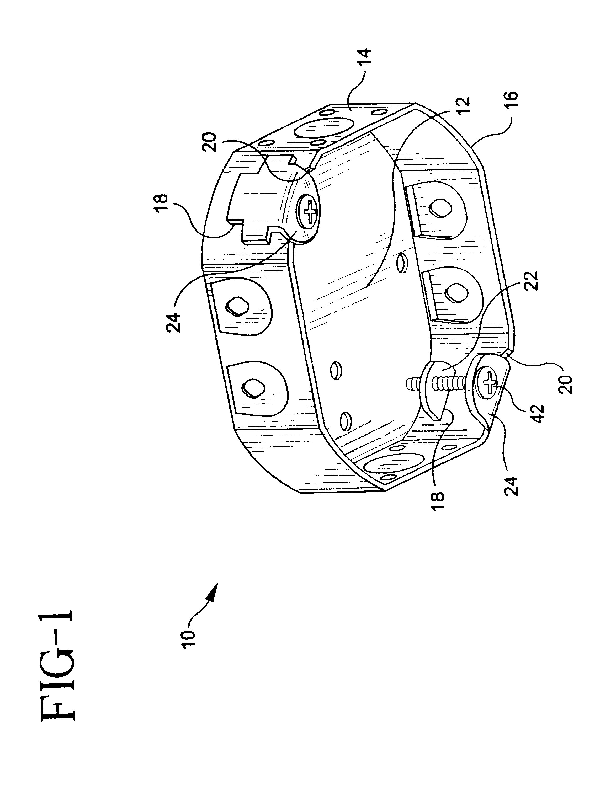
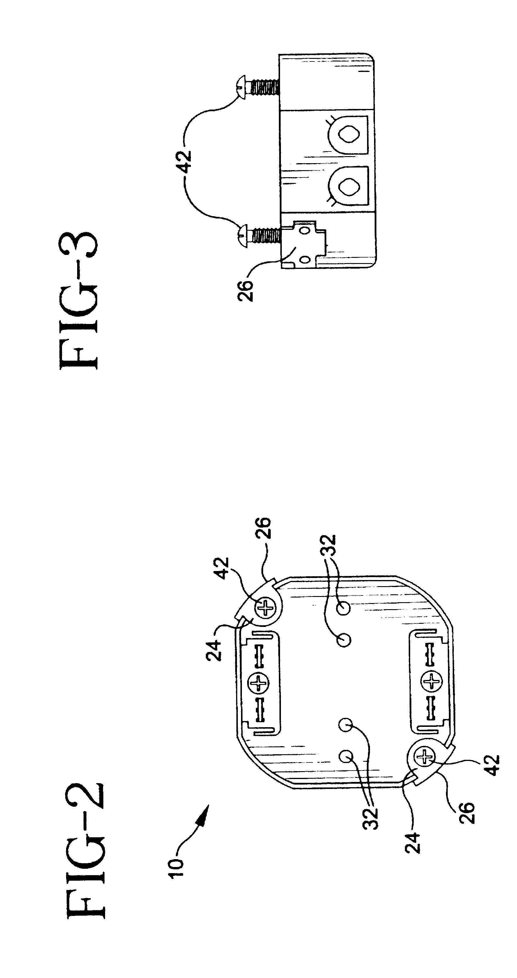
In the preferred embodiment of this invention, box 10 is generally octaganol in shape, as best seen in FIG. 2. A pair of slots 18, best seen in FIG. 10, are formed in opposite sides of box 10, as are a pair of recesses 20 formed in edge 16. Each slot 18 and its accompanying recess 20 are specially adapted to receive ears 22 and 24, respectively, of ear lug 26, best seen in FIGS. 7-9. As seen in FIG. 9, ears 22 and 24 are spaced apart and separated by a web portion 28, which preferably...


PUM


Abstract

An improved electrical ceiling box including a top portion bounded by a peripheral side portion, with a pair of diametrically opposed ear lugs rigidly secured to the side portion. Each ear lug has a pair of ears integrally formed therewith extending inwardly into the interior cavity of the box. A first ear fits within a recess formed in the bottom edge of the box, while a second ear extends through a slot formed in the side portion of the box. The second ear has a mounting hole formed therein adapted for threaded engagement with a self-tapping screw, while the first ear has a receiving hole formed therethrough for supporting the distal end of the screw. In a preferred embodiment, the box has a substantially hexagonal configuration. In an alternative embodiment, the box has a circular configuration and is shallower, thereby eliminating the need for a pair of slots for receiving the first ears. Preferably, the ear lugs are formed from a heavier gauge material than the remainder of the box for improved strength and resistance to breakage from fatigue.

Description

FIELD OF THE INVENTIONThis invention relates generally to electrical ceiling boxes and, more particularly, to an electrical box for mounting and supporting a ceiling fan, having improved mounting lugs for engaging the screws used to secure a ceiling fan.BACKGROUND OF THE INVENTIONCeiling fans have become increasingly popular in both commercial and residential settings as a means for improving air circulation and, in many instances, reducing overall electrical consumption. Ceiling fan mounting assemblies come in a variety of configurations, but the vast majority are designed to be secured to a conventional electrical outlet box installed in a ceiling, i.e., a ceiling box. Conventional ceiling boxes have a pair of inwardly extending ears (flanges) integrally formed with the side portion, with each ear having a threaded hole for engaging a mounting screw used to support a ceiling fan. For ceiling fans, conventional ceiling boxes do not provide sufficient strength to serve as support st...

Claims


Application Information

Patent Timeline
Patent Type & Authority Patents(United States)
IPC IPC(8): H02G3/20H02G3/18F04D25/08H02G3/08
CPCH02G3/20
Inventor BORDWELL, MARK A.MCCUTCHEON, JAMES D.
Owner THOMAS & BETTS INT INC
Why Eureka
Try Eureka