Dual interleaved DC to DC switching circuits realized in an integrated circuit

a switching circuit and integrated circuit technology, applied in the direction of electric variable regulation, process and machine control, instruments, etc., can solve the problem that the converter has not been realized in the integrated circuit form

Inactive Publication Date: 2003-06-10
MAXIM INTEGRATED PROD INC
View PDF17 Cites 33 Cited by
  • Summary
  • Abstract
  • Description
  • Claims
  • Application Information

AI Technical Summary

Benefits of technology

Dual interleaved DC to DC switching circuits realizable in an integrated circuit form, capable of monitoring individual inductor current using only one current sense resistor and providing automatic duty cycle adjustment to keep the inductor currents in the interleaved DC to DC switching circuits balanced are disclosed. The preferred embodiment includes a gain error amplifier, an integral error amplifier, and a differentiator error amplifier and circuits for controlling the nominal duty cycle, with the gain error amplifier, integral error amplifier and differentiator error amplifier being adjustable independently by external components. The circ...

Problems solved by technology

While dual interleaved converters are known in the prior art, such converters have not been realized in integrated circuit form because of various probl...

Method used


Image

  • Dual interleaved DC to DC switching circuits realized in an integrated circuit
  • Dual interleaved DC to DC switching circuits realized in an integrated circuit
  • Dual interleaved DC to DC switching circuits realized in an integrated circuit

Examples


Embodiment Construction

The preferred embodiment of the present invention is intended for use for a buck converter, and accordingly, the same will be described in detail with respect to such converters. However, it is to be understood that the principles of the present invention are also applicable to other types of converters, including step-up converters, as are also well known in the art.

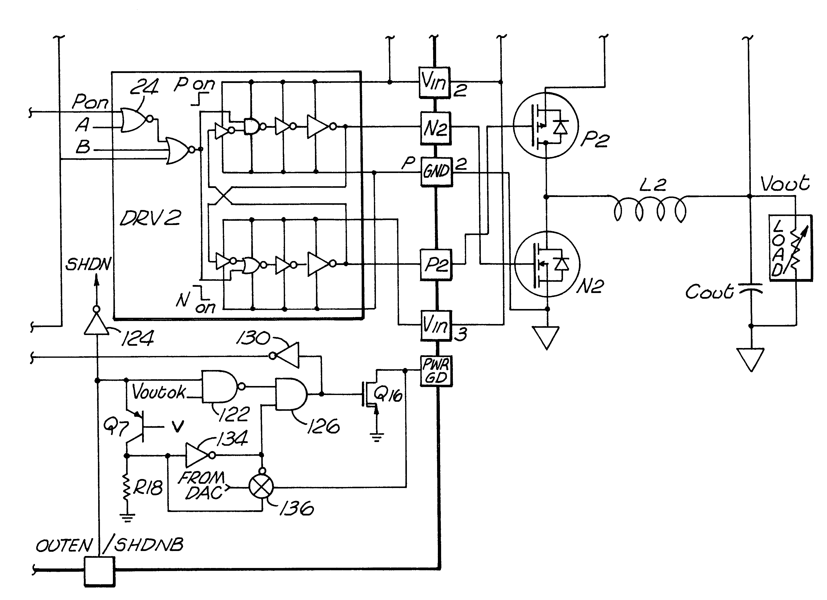
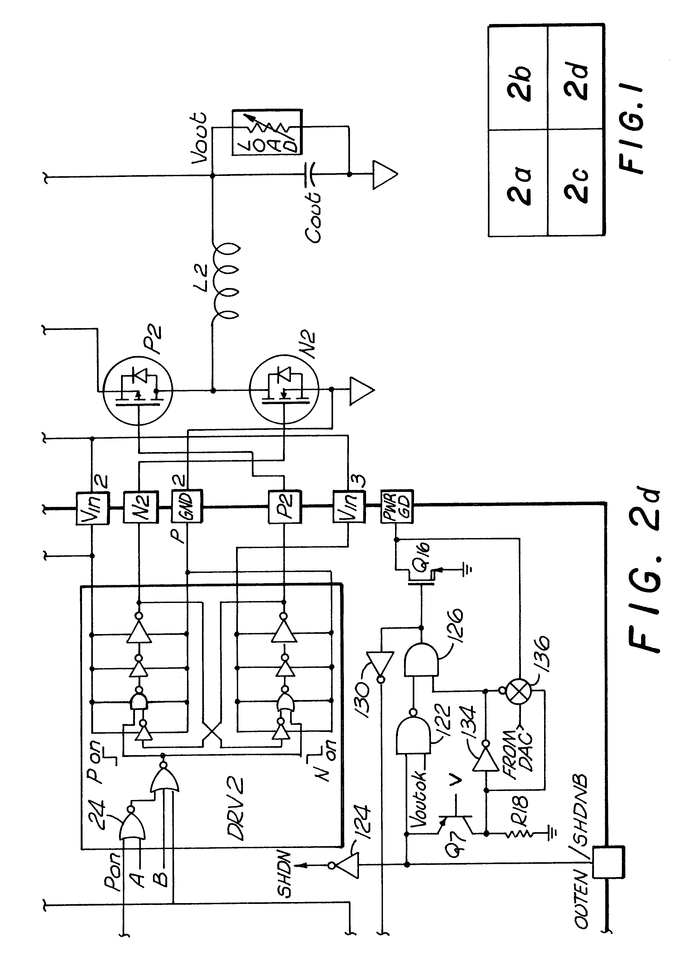
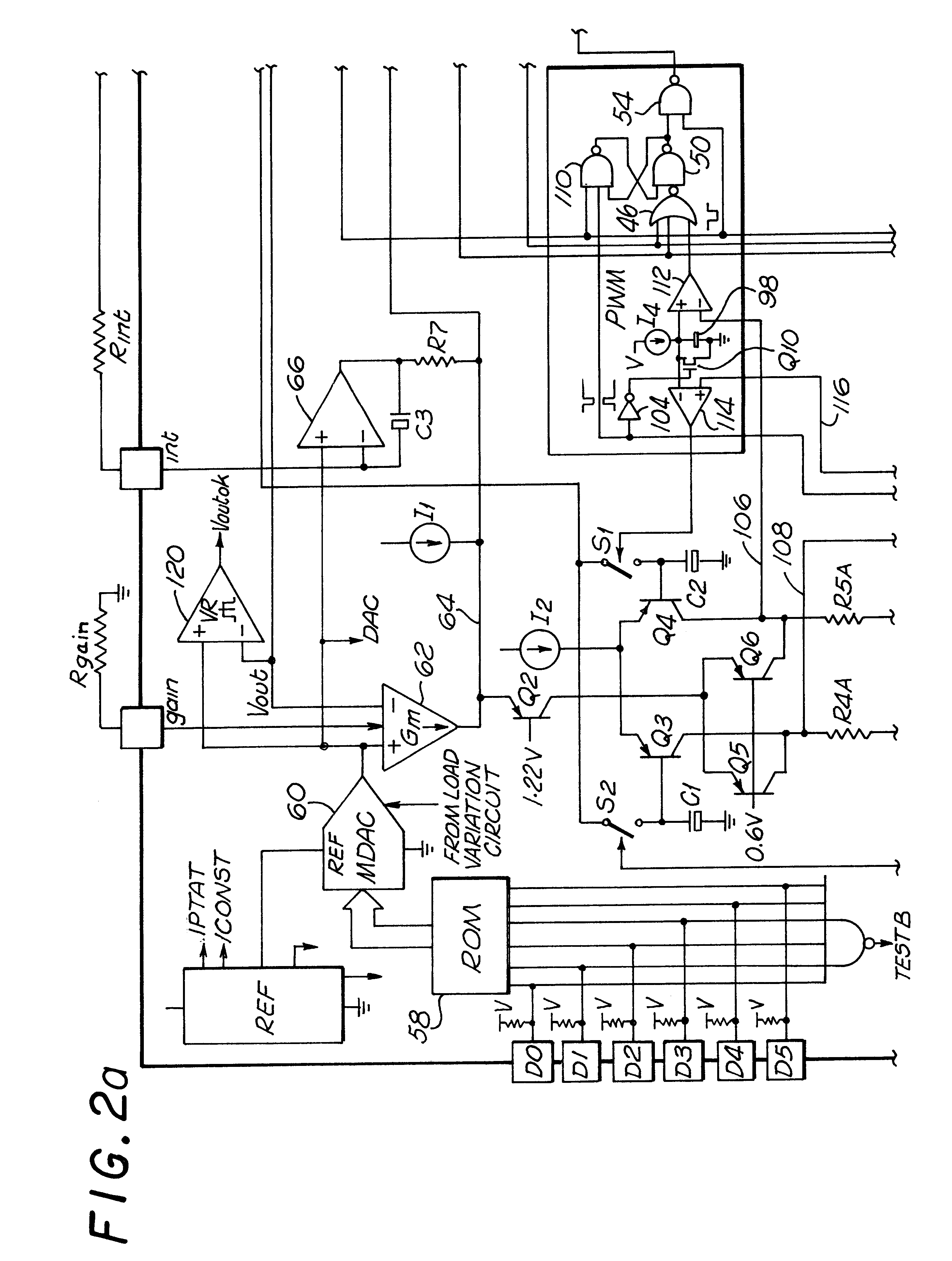
Now referring to FIG. 2, comprised of FIGS. 2a through 2d, a circuit diagram of the preferred embodiment may be seen. (FIGS. 2a through 2d are drawn in a proportion allowing the fitting together of the Figures in the manner illustrated in FIG. 1 to form the overall circuit of FIG. 2.) In this embodiment, the input voltage Vin is provided through optional resistor Rin and optional inductor Lin to capacitor Cin and the current sensing resistor Rsense. The resistor Rin, the inductor Lin and the capacitor Cin provide filtering of the switching noise to reduce the feedback of that noise to the power source of the input volta...


PUM


Abstract

Dual interleaved DC to DC switching circuits realizable in an integrated circuit form, capable of monitoring individual inductor current using only one current sense resistor and providing automatic duty cycle adjustment to keep the inductor currents in the interleaved DC to DC switching circuits balanced. The preferred embodiment includes a gain error amplifier, an integral error amplifier, and a differentiator error amplifier and circuits for controlling the nominal duty cycle, with the gain error amplifier, integral error amplifier and differentiator error amplifier being adjustable independently by external components. The circuit further includes a high speed load regulation circuit that momentarily overrides the control circuitry to take over control of the interleaved converters during sudden load changes, such control also being programmable. The circuit further includes a load variation circuit to target the output voltage of the circuit to an optimal value with load to better keep the output voltage within a targeted range in the event of major step changes in the load. The disclosed embodiment is for two interleaved buck converters, though the principles of the invention are applicable to interleaved step up converters and the interleaving of more than two converters.

Description

BACKGROUND OF THE INVENTION1. Field of the InventionThe present invention relates to the field of DC to DC converters.2. Prior ArtThe preferred embodiment of the present invention pertains to DC-DC buck (step-down) converters. These are switching regulators that switch one end of an inductor between the input power supply and ground. The inductor spends T.sub.ON seconds connected to the input power supply and the remainder of the time connected to ground. If T is the total time for one cycle, then the output voltage (at the other end of the inductor), if filtered, will average T.sub.on / T.times.V.sub.IN.Filtering normally entails connecting a capacitor from the output side of the inductor to ground. The amount of ripple voltage at the output varies with V.sub.IN, T, L, C and V.sub.OUT.A dual interleaved converter uses two buck converters running in parallel, but switched 180.degree. out of phase. Thus halfway through the first cycle of one inductor, the second inductor is switched h...

Claims


Application Information

Patent Timeline
IPC IPC(8): H02M3/158H02M3/04H02M3/155
CPCH02M3/1584
Inventor SCHAFFER, GREGORY L.
Owner MAXIM INTEGRATED PROD INC
Why Eureka
Try Eureka