
Derivation of studio camera position and motion from the camera image

a technology of motion and camera image, applied in image enhancement, color signal processing circuit, instruments, etc., can solve the problem of impracticality of providing an appropriate number of well-distributed reference points in the imag

Inactive Publication Date: 2004-02-10
BRITISH BROADCASTING CORP
View PDF20 Cites 58 Cited by
  • Summary
  • Abstract
  • Description
  • Claims
  • Application Information

AI Technical Summary

Benefits of technology

This approach does not require special markers or feature points in the image, merely sufficient detail to allow simple estimation of global motion parameters. Thus it should be able to work with a wide range of picture material. All that is required is measurement of the initial focal length (or angle subtended by the field of view) and the initial position and angle of view of the camera.
The approach described may be extended to more general situations (giving more freedom on the type of camera motion allowed) if other information such as image depth could be derived [Brandi et al. 1990]. Additional information from some sensors on the camera (for example to measure the degree of zoom) may allow more flexibility.
The key signal may be used to remove foreground objects from the image prior to the motion estimation process. Thus the motion of foreground objects will not confuse the calculation.

Problems solved by technology

Consideration of the operational constraints in a TV studio suggested that providing an appropriate number of well-distributed reference points in the image would be impractical: markers would have to be placed throughout the scene at a range of different depths in such a way that at a significant number were always visible, regardless of the position of the camera or actors.

Method used


Image

  • Derivation of studio camera position and motion from the camera image
  • Derivation of studio camera position and motion from the camera image
  • Derivation of studio camera position and motion from the camera image

Examples


embodiment 2

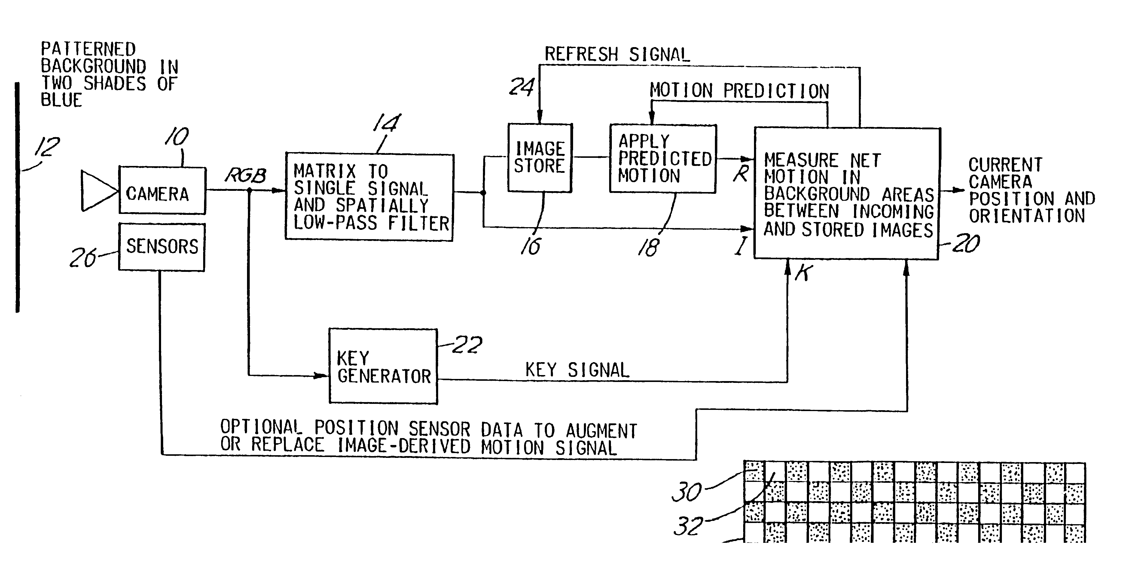
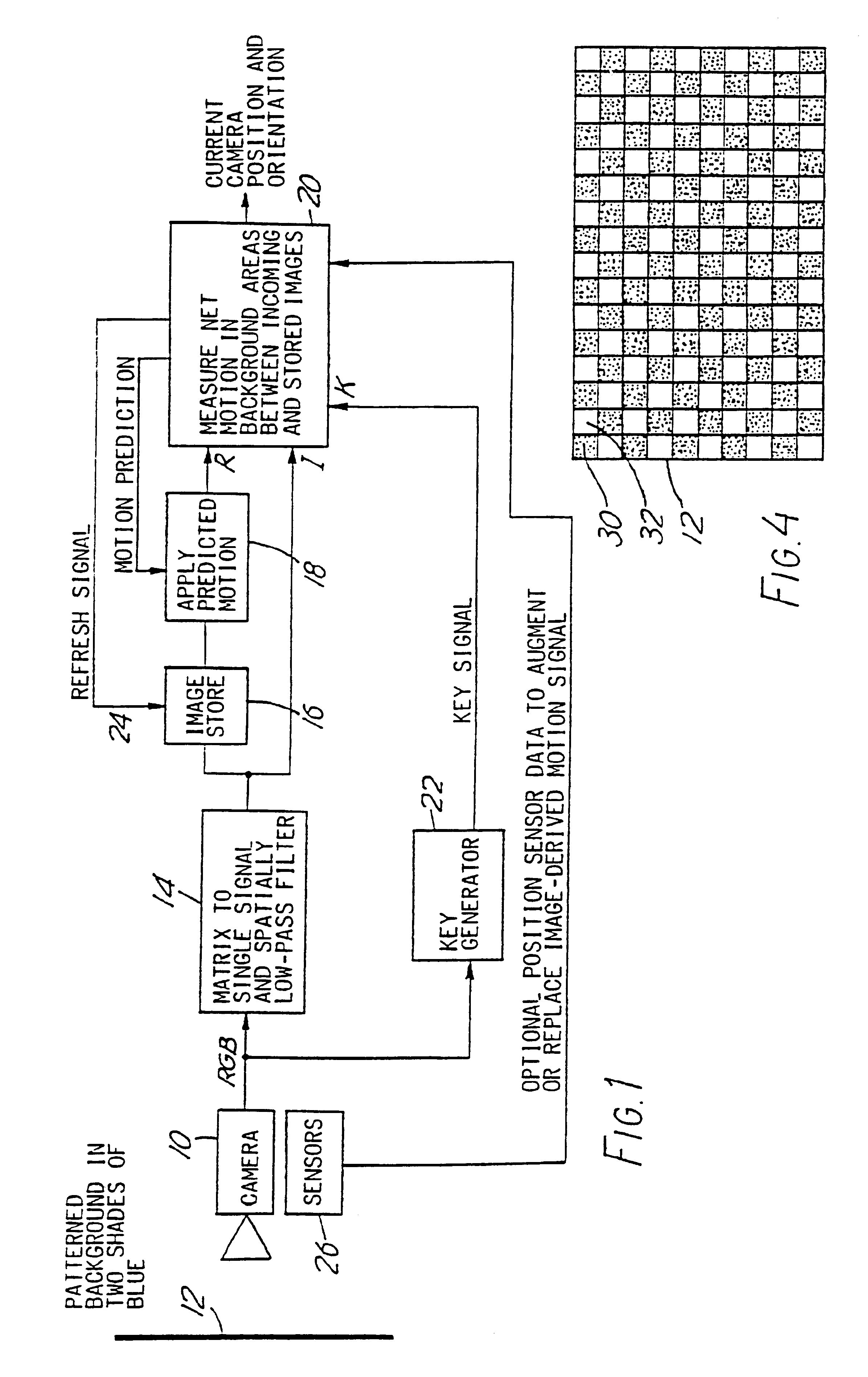
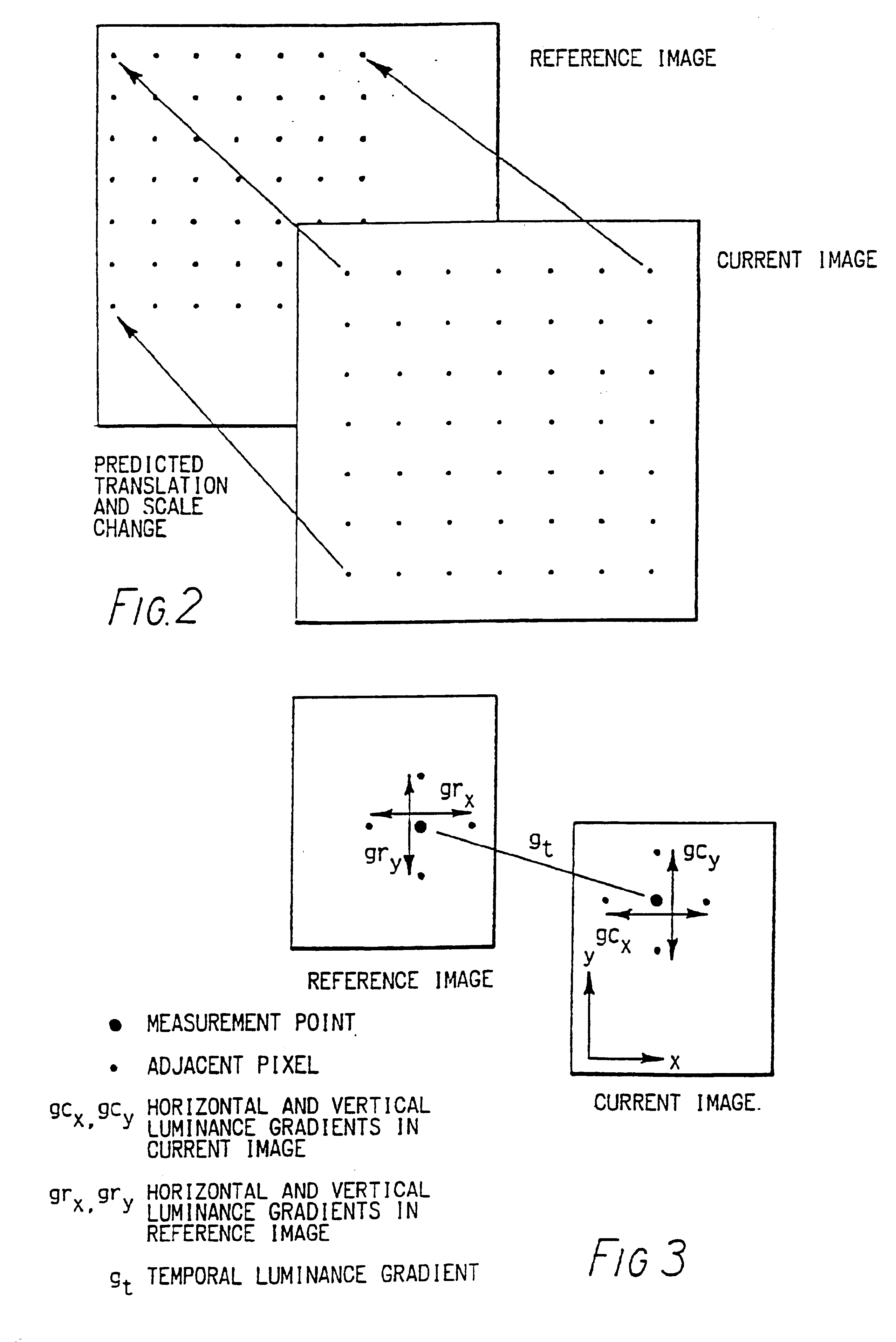
ation of Global Motion Parameters An alternative and preferred method of determining global translation and scale change is to derive them directly from the video signal. A method of doing this is described in reference 7 by [Wu and .[.Kittel.]. .Iadd.Kittler .Iaddend.1990]. We have extended this method to work using a stored reference image and to use the predicted motion values as a staging point. Furthermore, the technique is applied only at a sub-set of pixels in the image, that we have termed measurement points, in order to reduce the computational load. As in the previous embodiment the RGB video signal is matrixed to form a single-component signal and spatially low-pass filtered prior to processing. As described previously, only areas identified by a key signal as background are considered.

The method is applied by considering a number of measurement points in each incoming image and the corresponding points in the reference image, displaced according to the predicted translat...


PUM


Abstract

Studio camera position and motion may be derived from the camera image by separating out the background and deriving from a background having a number of areas of hue and / or brightness different from adjacent areas estimates of movement from one image to the next. The initial image is used as a reference and amended with predicted motion value. The amended image is compared with incoming images and the result used to derive translation and scale change information. Once the proportion of the reference image contained in an incoming image falls below a threshold a fresh reference image is adopted.

Description

FIELD OF THE INVENTIONThis invention relates to the derivation of information regarding the position of a television camera from image data acquired by the camera.BACKGROUND TO THE INVENTIONIn television production, it is often required to video live action in the studio and electronically superimpose the action on a background image. This is usually done by shooting the action in front of a blue background and generating a `key` from the video signal to distinguish between foreground and background. In the background areas, the chosen background image can be electronically inserted.One limitation to this technique is that the camera in the studio cannot move, since this would generate motion of the foreground without commensurate background movement. One way of allowing the camera to move is to use a robotic camera mounting that allows a predefined camera motion to be executed, the same camera motion being used when the background images are shot. However the need for predefined mo...

Claims


Application Information

Patent Timeline
IPC IPC(8): G06T7/20G06T7/00H04N7/26H04N5/14G06V10/147
CPCG06T7/20G06T2207/30244H04N5/144H04N5/2224H04N19/527H04N19/53H04N19/54G06T7/70G06V10/147
Inventor THOMAS, GRAHAM ALEXANDER
Owner BRITISH BROADCASTING CORP
Learn More