Adjust bit determining circuit

Inactive Publication Date: 2005-04-05
FUJITSU LTD
View PDF13 Cites 0 Cited by
  • Summary
  • Abstract
  • Description
  • Claims
  • Application Information

AI Technical Summary

Benefits of technology

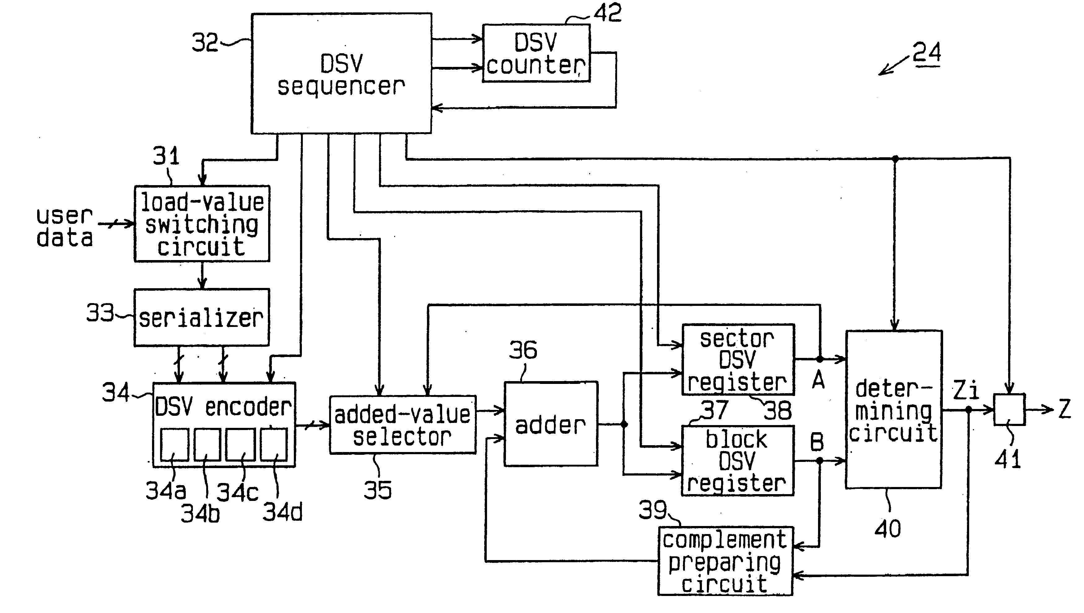
Broadly speaking, the present invention relates to a method and circuit of determining the a

Problems solved by technology

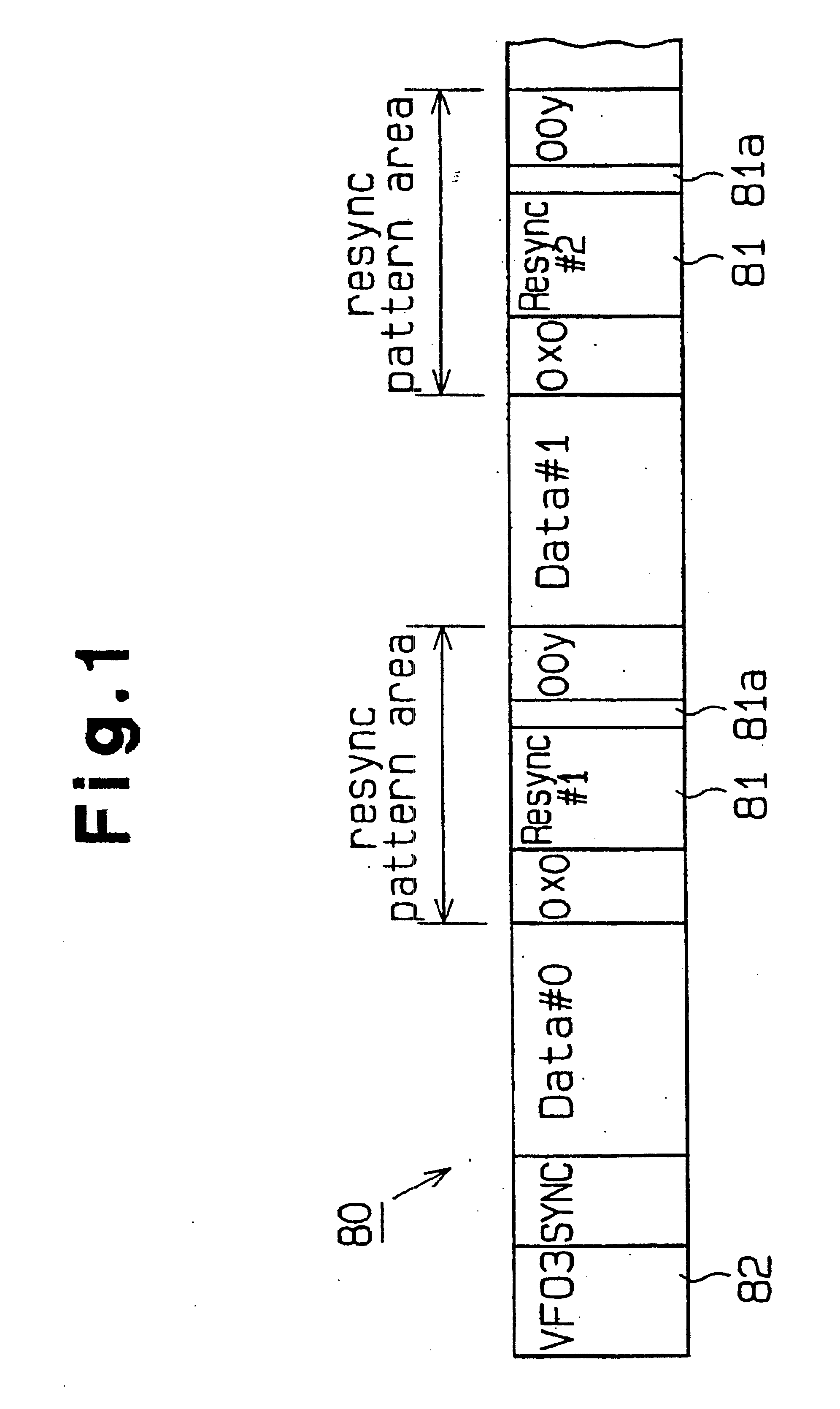
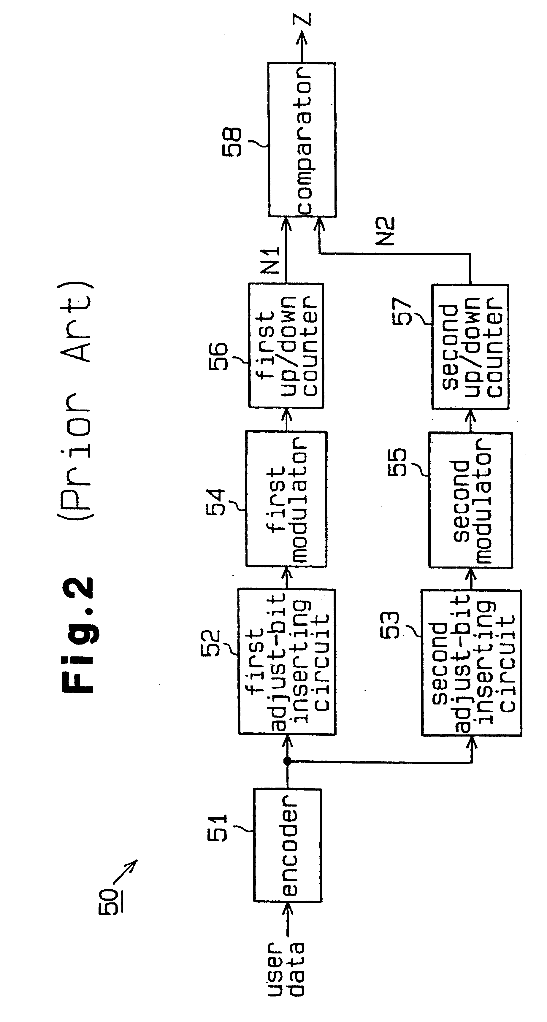
The adjust-bit determining circuit requires two groups of circuits for DSV computation: the circuits 52, 54 and 56 for performing DSV computation based on data having a “1” previously recorded in the adjust bit 81a, and the circuits 5

Method used


Image

  • Adjust bit determining circuit
  • Adjust bit determining circuit
  • Adjust bit determining circuit

Examples


Embodiment Construction

One embodiment of the present invention will be now described with reference to FIGS. 3 through 7.

FIG. 3 shows the structure of an optical disk apparatus 10, which writes data on an optical disk 11 recording medium and reads recorded data therefrom. Data is recorded using the PWM system on the optical disk 11 by this optical disk apparatus.

The optical disk 11 is rotated by a first motor 12 under the control of a rotation control circuit 13. A drive head 14 is driven by a second motor 15 to move in the radial direction of the optical disk 11. The second motor 15 is controlled by a radial movement control circuit 16. The drive head 14 includes an optical pickup which writes data on the optical disk 11 and reads recorded data therefrom. A drive head control circuit 17 controls the drive head 14 in order to write data on and read data from the optical disk 11. The drive head 14 outputs data, read from the optical disk 11, to a disk controller 19 via a signal processor 18.

The disk contro...


PUM


Abstract

A recording medium for a computer contains sectors, each of which represents a section of data that has originally been supplied by a user. As the user data is sent to the recording medium from the memory of the computer, an adjust bit determining circuit determines the adjust bit for a block of the write data. The adjust bit-value is such that the sum of the DC levels for the write data at a given point is equal to zero or approaches zero. The user data is converted using RLL(1,7) codes and PWM is performed to derive the write data. The circuit includes an encoder for receiving the user data two bits at a time. The encoder outputs DSV values for the 2-bit user data. A first circuit group for accumulating the DSV values from the encoder is used acquire block DSV values of data belonging to the plurality of blocks of the data section. A second circuit group accumulates these block DSV values computed by the first circuit group and calculates a temporary sector DSV value. This temporary sector DSV value represents a DSV value ranging from the head block of the data section up to the current block which is being processed. The first and second circuit groups are controlled by a DSV sequencer. A determining circuit is coupled to the first and second circuit group for comparing the sector DSV value with a block DSV value for a next block following the current block.

Description

BACKGROUND OF THE INVENTION1. Field of the InventionThe present invention relates generally to the preparation and writing of data from the memory of a computer to a storage medium. More specifically, the invention relates to a method and circuit of determining the adjust bit of write data to be recorded on a recording medium by a pulse width modulation (PWM) system.2. Description of the Related ArtRecently, there has been an increasing demand for higher recording densities on recording media like magneto-optical disks. Instead of the conventional PPM (Pit Position Modulation) system, the PWM system has been receiving a great deal of attention these days as a method of recording data on a recording medium with a high density.As a method of recording data on a recording medium, the PWM system is superior to the PWM system in improving the recording density. The PWM system records data in such a manner that the sum of the DC levels become zero or a value close to zero so as to ensure ...

Claims


Application Information

Patent Timeline
IPC IPC(8): H03M5/00G06F3/08G11B20/10G11B20/14H03M7/46H04L25/49
CPCG11B20/10G11B20/1426H03M7/46H04L25/4902H04L25/4906H04L25/4908G11B20/14
Inventor ISHIGURO, MASAYUKI
Owner FUJITSU LTD
Why Eureka
Try Eureka