The rapid increase
in vehicle usage around the world has concomitantly increased parking pressure in most cities.
The increasing housing density in many areas has further exacerbated parking problems.
Parking can be particularly problematic for those who need to come and go from a place of business in a city throughout the day because each time they return to their place of business they often have to spend a considerable amount of time searching for a parking place.
Difficulties arise as the proportion of reserved parking places in the car park or parking building increases, concomitantly reducing the parking places available to the public.
This frequently leads to members of the public using reserved parking places either through ignorance or indifference.
Often drivers resort to a variety of means to
gain unauthorized entry to parking lots, parking buildings or public areas in an effort to find a parking place and / or avoid paying for use of the parking place.
In some areas, the problem of unauthorized parking has become so serious that vehicles parked without
authorization have been towed away and impounded, often leading to damage of the vehicle and occasioning legal action.
While these methods and devices for stopping unauthorized entry and exit to and from car parks and parking buildings are quite effective, they are usually not foolproof and they cannot be used to protect individual parking spaces within the parking building or car park.
Furthermore if the device breaks down or malfunctions, potentially hundreds of people can be inconvenienced by being prevented from entering or leaving the car park or parking building.
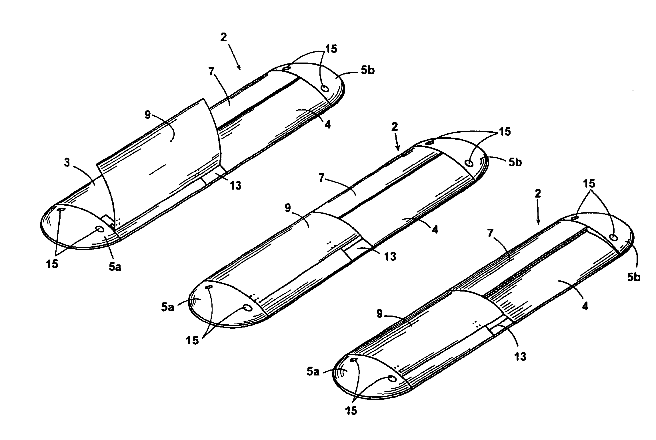
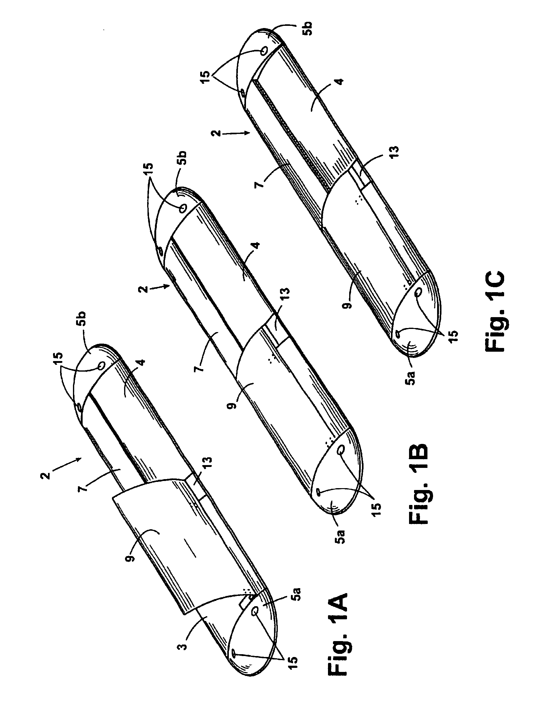
Individual parking places are sometimes secured from unauthorized use by manually operated devices.
Accordingly an unauthorized driver cannot drive into the empty parking place when the hoop or pair of hoops are raised and locked in place.
The principal
disadvantage of such hoops is that they require manual operation and are thus most suited for use on parking places for long term parking; the hoops are extremely unsuitable for parking places which are used on a regular basis because the user must constantly get in and out of their vehicle to manually raise and lower the hoop.
Consequently the
metal hoops are particularly inconvenient for use by the elderly or disabled.
Additionally, it is not always possible to temporarily stop a vehicle in a roadway or similar approach to the particular parking place while the driver gets out of the vehicle to lower the hoops to allow access to the parking space.
In use it is manually raised to a vertical position and locked into place and accordingly it suffers from the same disadvantages as the hoops described above.
One of the disadvantages of this type of
system is that both the raising and lowering of the
metal loop requires power from the external power source and consequently frequent replacing or recharging of the battery is required or main power must be supplied to the unit necessitating
electrical wiring.
A further
disadvantage suffered by the SECURAPARK device and other devices of the prior art is that special skills are required for their installation and in general it is necessary to carry out external works on
a site prior to their installation.
Where specialists are required to install such devices, the overall cost of each unit is increased.

