Thermocycler and lifting element

a technology of lifting element and rotating rod, which is applied in the field of rotating rod, can solve the problems of requiring suitable and correspondingly heavy and expensive handling devices for applying relatively large forces, affecting the operation of the machine, so as to facilitate the manual removal

Inactive Publication Date: 2007-04-17
APPLERA
View PDF83 Cites 4 Cited by
  • Summary
  • Abstract
  • Description
  • Claims
  • Application Information

AI Technical Summary

Benefits of technology

[0004]It has been found that, as a result of the measures according to the invention, the microtitre plate is raised after removal of the cover, which permits convenient gripping and lifting thereof without application of force. T...

Problems solved by technology

In known thermocyclers of the generic type, there is the problem that the microtitre plate which, in the interests of good heat transfer, rests closely against the heating surface frequently becomes baked onto it and can then be detached from it only with very great...

Method used


Image

  • Thermocycler and lifting element
  • Thermocycler and lifting element
  • Thermocycler and lifting element

Examples


Embodiment Construction

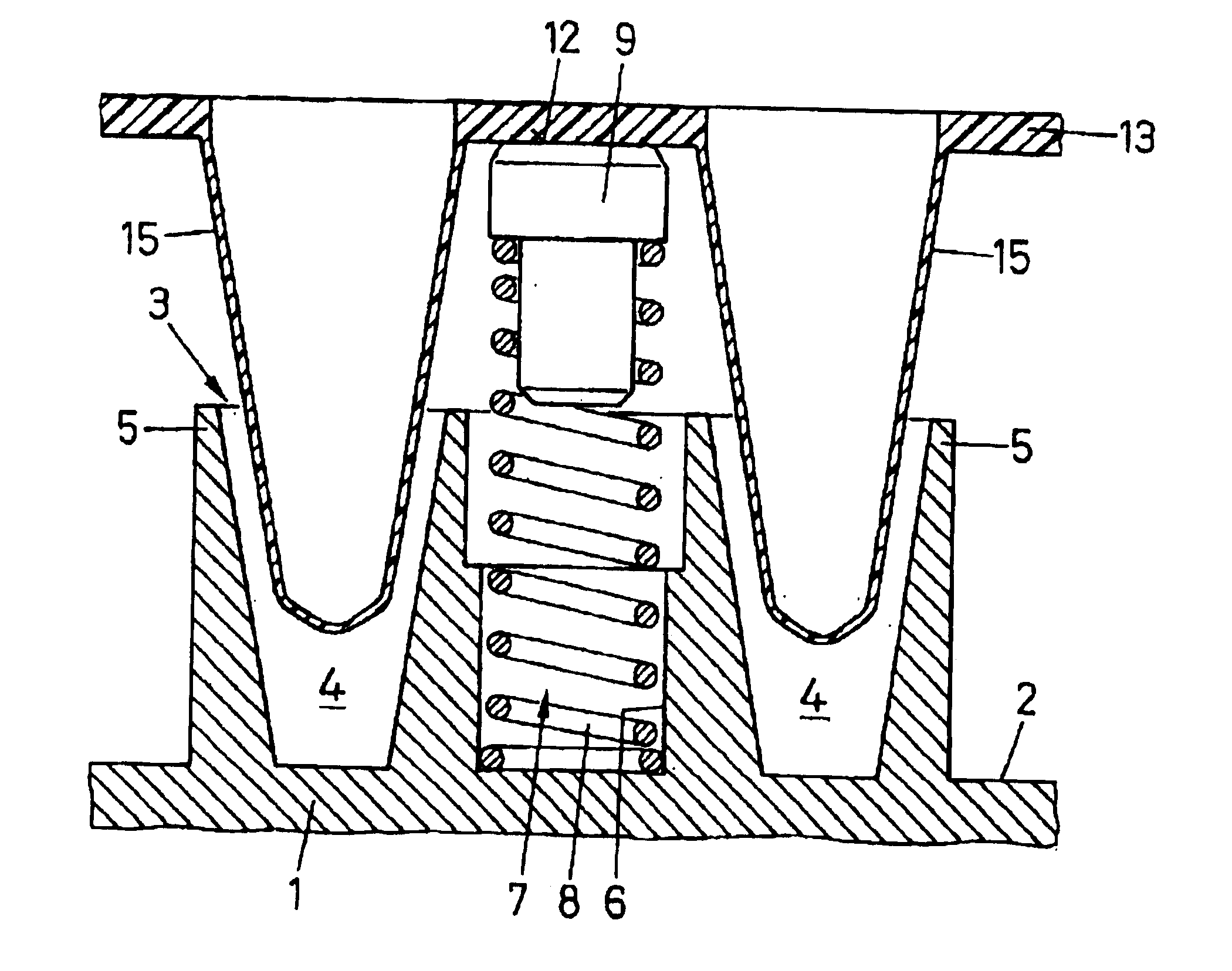
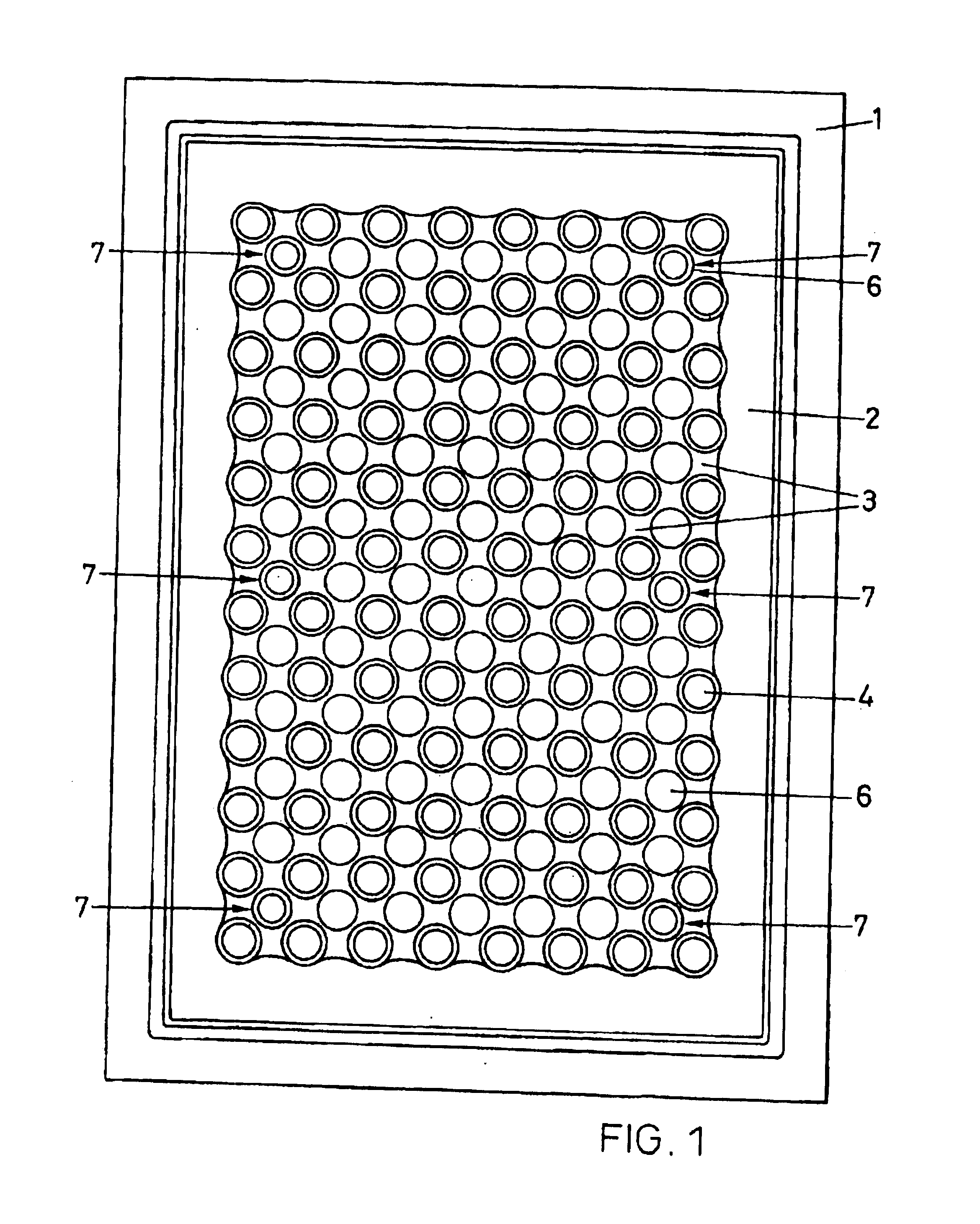
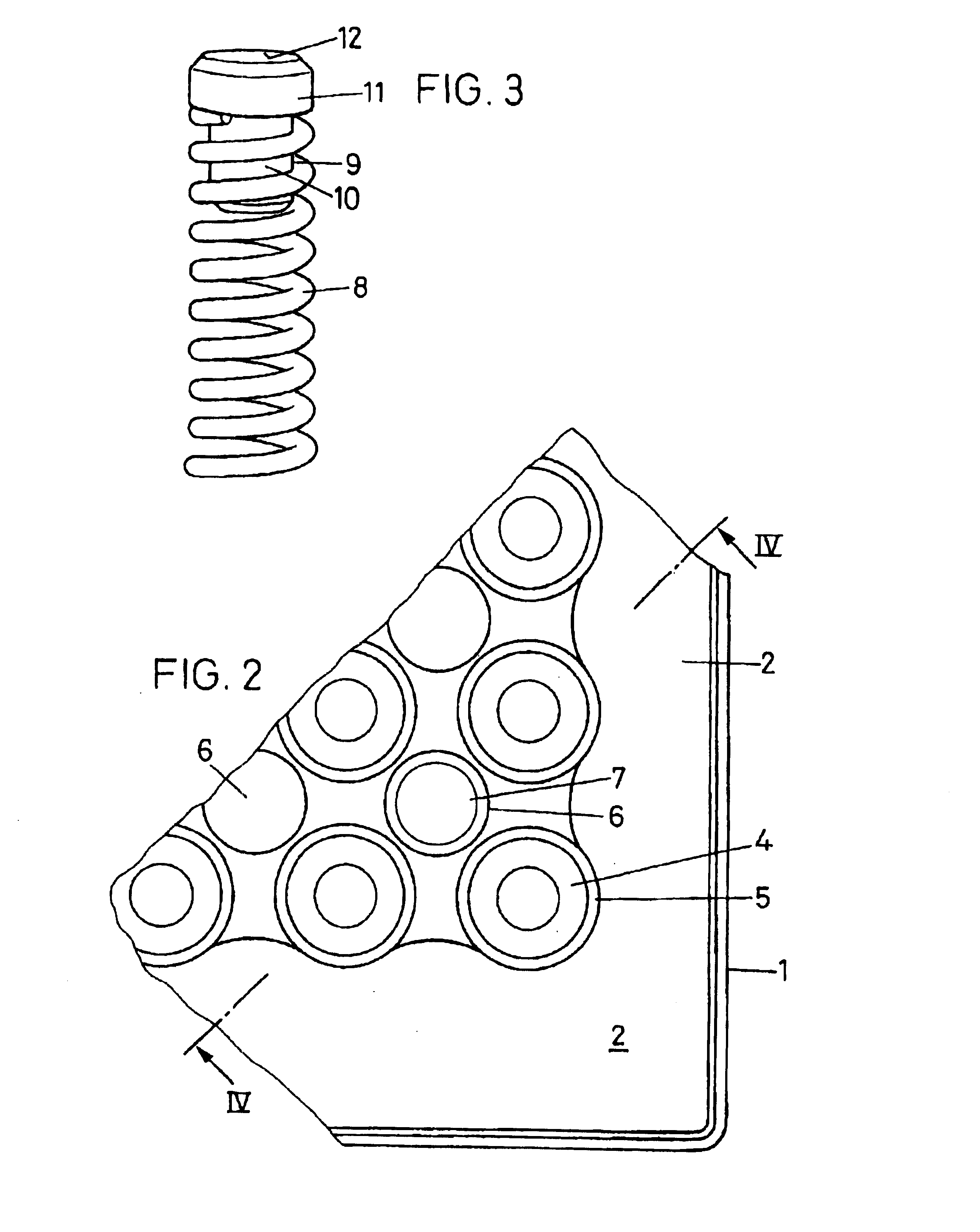
[0012]The thermocycler, which may be suitable, for example, for holding an 8×12 microtitre plate having the dimensions 85 mm×130 mm, has a heating plate 1 which forms a heating surface 3 which is surrounded by an edge strip 2 and is somewhat higher than said edge strip and in which round indentations 4 are arranged in a regular square grid, each of which indentations is surrounded by an all-round wall 5 (FIG. 2) projecting beyond the base level of the heating surface 3. In each case, a blind hole 6 is provided between four indentations 4.

[0013]Six lifting elements 7 are arranged in six of the blind holes 6 altogether, distributed approximately uniformly over the heating surface 3. Each of the lifting elements 7 consists (FIG. 3) of a cylindrical coil spring 8 of stainless steel, the lowermost winding of which is somewhat wider than the other windings, and a contact pin 9 whose approximately cylindrical shaft 10 is inserted into the upper end of the coil spring 8 and is held therein ...


PUM


Abstract

Some of the blind holes (6) between indentations (4) of a heating surface (3) contain lifting elements (7) which, after opening of a cover, release a microtitre plate (13) from the heating surface (3) and raise said microtitre plate about 2 to 3 mm, so that it can be removed without application of force. Each lifting element (7) consists of a coil spring (8) and a contact pin (9) made of, for example, PEEK which is inserted into said coil spring and presses with a round flat abutting surface (12) against the lower surface of the microtitre plate (13). The spring constant of the lifting element (7) is about 6 N/mm.

Description

FIELD OF THE INVENTION[0001]The invention relates to a thermocycler. Such devices are used for subjecting the content of the wells of microtitre plates to temperature cycles which initiate specific chemical reactions. It also relates to lifting elements for use in thermocyclers.PRIOR ART[0002]In known thermocyclers of the generic type, there is the problem that the microtitre plate which, in the interests of good heat transfer, rests closely against the heating surface frequently becomes baked onto it and can then be detached from it only with very great difficulty. This either necessitates complicated manipulations or requires suitable and correspondingly heavy and expensive handling devices for applying relatively large forces of 150 N or more. A possible aid is the use of Teflon spray, which can prevent the microtitre plate from baking on. However, this must be repeated for every plate and complicates the procedures.SUMMARY OF THE INVENTION[0003]It is the object of the invention ...

Claims


Application Information

Patent Timeline
IPC IPC(8): B01L3/00B01L7/00C12M1/38G01N35/00H05B3/22B01J19/00B01L9/00F28F13/00
CPCB01J19/0093B01J2219/00788B01J2219/00804B01J2219/00869B01J2219/00873B01L7/52B01L9/523B01L2200/04B01L2300/0829F28F13/00Y10S435/809
Inventor ELSENER, DONATRYSER, WERNERRYSER, DANIEL
Owner APPLERA
Why Eureka
Try Eureka