Pipe joint made of resin

Inactive Publication Date: 2007-04-24
NIPPON PILLAR PACKING CO LTD
View PDF14 Cites 4 Cited by
  • Summary
  • Abstract
  • Description
  • Claims
  • Application Information

AI Technical Summary

Benefits of technology

[0033]According to the present invention, a cylindrical overlapping piece overlapped with the receiving surface may be continuously formed on the pressing portion of the pushing ring, by mounting the overlapping piece on the receiving surface on a side of the pipe to increase the diameter in a state of widening a ti

Problems solved by technology

In such a pipe joint made of resin, creep and stress relaxation are generated with time on the joint body 81 made of resin and the pushing ring 83, the pipe 7 or the like, whereby the sealing surface pressures of the primary sealing portion S1 and the secondar

Method used


Image

  • Pipe joint made of resin
  • Pipe joint made of resin
  • Pipe joint made of resin

Examples


Example

[0051]Referring now to the drawing, preferred embodiments of the present invention are described below.

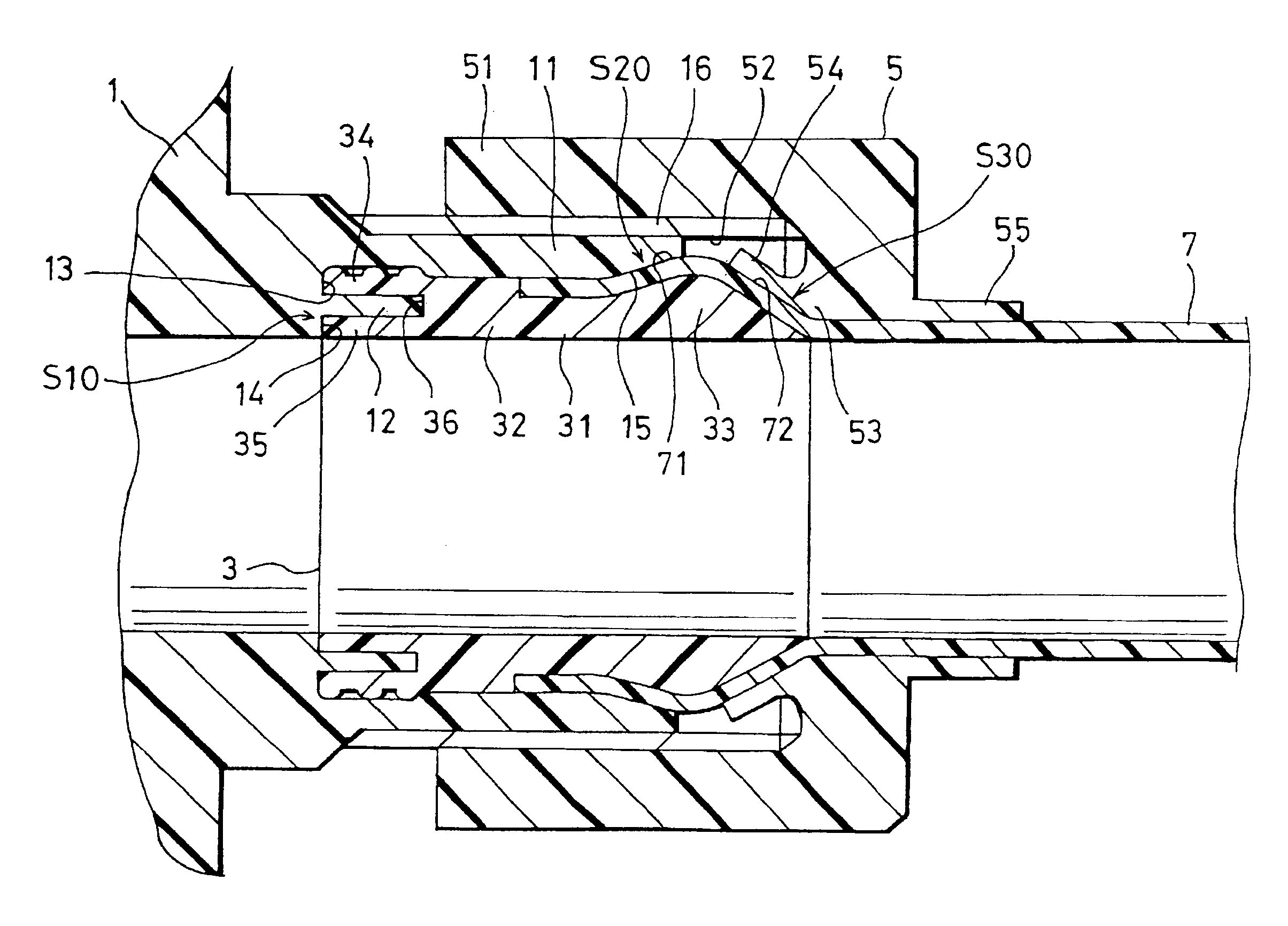
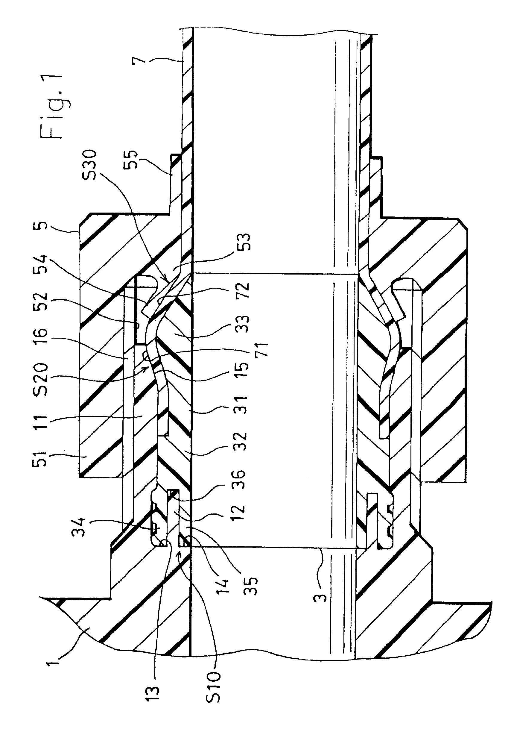
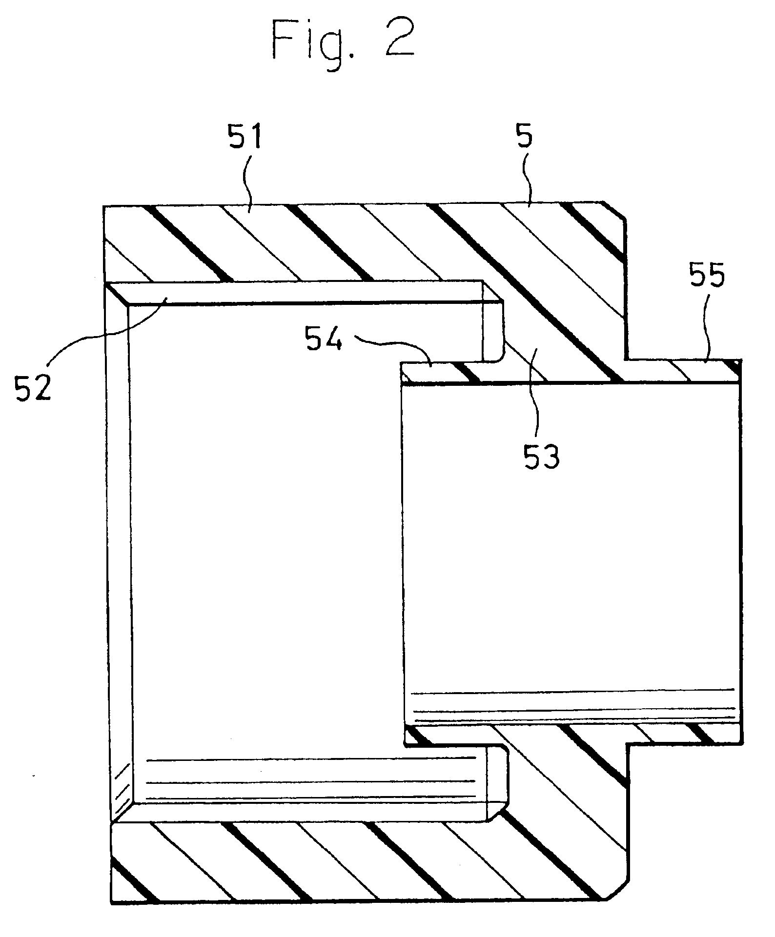
[0052]A pipe joint made of resin as shown in FIGS. 1 and 7 includes a cylindrical joint body 1, a cylindrical inner ring 3, and a cap nut shaped pushing ring 5. The joint body 1, the inner ring 3 and the pushing ring 5 are individually made of a synthetic resin such as PFA (perfluoro-alkoxyfluoro plastics), PTFE (polytetrafluoroetylene), ETFE (etylene-tryfluoro-etylene), CTFE (chloro-tryfluoro-etylene), ECTEE (etylene-chloro-tryfluoro-etylene), having a superior feature in resistance to chemicals and resistance to heat.

[0053]The joint body 1 has a cylindrical receiving port 11 on at least one axial end portion thereof. The joint body 1 is provided with a short cylindrical portion 12 protruding in the inside area defined by the receiving port 11, and being concentric with the receiving port 11, forming an annular groove portion 13 disposed between the cylindrical portion 12 and the ...


PUM

PropertyMeasurementUnit
Diameteraaaaaaaaaa

Abstract

The present invention relates to a pipe joint made of resin used for laying pipes in which a high-purity liquid, ultra pure water or the like flow. According to the pipe joint of the present invention, a sealing surface pressure is generated in both axial and radial directions, providing thereby an excellent sealing property for a long period, and facilitate controlling a torque for fastening a pushing ring. The pipe joint made of resin according to the present invention comprises a joint body having a receiving port, a cylindrical portion, an annular groove portion and a stepped surface. An inner ring forcedly inserted by the pushing ring is provided with an outer projection, an inner projection and an annular recessed portion. On at least one portion among axially opposed portions of each surface, an axial sealing portion is disposed. On at least one portion among radially opposed portions of each surface, an radial sealing portion is disposed. The joint body, the inner ring and the pushing ring are individually made of an optional synthetic resin selected among PFA, PTFE, ETFE, CTFE, and ECTFE.

Description

BACKGROUND OF THE INVENTION[0001]1. Field of the Invention[0002]The present invention relates to a pipe joint made of resin, and in particular, to a pipe joint applied to laying pipes for a high-purity liquid and ultra pure water treated in a production process in various technical fields such as the production of semiconductors, medical supplies and medicines, food processing and the chemical industry.[0003]2. Description of the Prior Art[0004]Conventionally, such pipe joints made of resin having a structure as shown in FIG. 8 are known. The known pipe joint made of resin comprises a joint body 81, an inner ring 82 and a pushing ring 83. The joint body 81 has a receiving port 84, a tapered receiving surface 85 projecting from a base portion of the receiving port 84, and a tapered receiving surface 86 disposed on a tip portion of the receiving port 84. Additionally, an outer periphery of the receiving port 84 is provided with a male thread portion 87. The inner ring 82 includes a co...

Claims


Application Information

Patent Timeline
IPC IPC(8): F16L25/00F16L19/04F16L47/04
CPCF16L19/041Y10S285/906F16L47/041F16L47/04F16L47/06
Inventor NISHIO, KIYOSHI
Owner NIPPON PILLAR PACKING CO LTD
Why Eureka
Try Eureka