Rotary shelf assembly mechanism having a post height adjustment device and a novel shelf construction and self retaining element for securing the shelves to the post

a technology of height adjustment device and assembly mechanism, which is applied in the direction of display hangers, dismountable cabinets, cabinets, etc., can solve the problems of not providing vertical adjustment, wasting cabinet space in the corner either above or below the kitchen counter, and the combination of elements is obviously more expensive than desired, so as to achieve the effect of easy adjustment of the height of the shelf assembly

Inactive Publication Date: 2007-11-13
REV A SHELF
View PDF28 Cites 13 Cited by
  • Summary
  • Abstract
  • Description
  • Claims
  • Application Information

AI Technical Summary

Benefits of technology

[0014]Accordingly, it is an object of the present invention to provide a rot...

Problems solved by technology

Such shelves are desirable because, without them, much cabinet space in the corner either above or below the kitchen counter is wasted due to the inaccessibility of items well back in the corner.
One of the problems encountered with such a structure is the variance of non-uniform distances between the top and bottom of the cabinet thus requiring some accommodation for the length of the post in order for the post and shelves to fit and function properly within the cabinet.
While the reference discloses a workable combination, it does require an end cap to slide over the upper end of the lower post thus allowing a key formed on the upper bracket to fit within the formed channel in the upper post, a combination of elements obviously more expensive than desired.
This fitting pr...

Method used


Image

  • Rotary shelf assembly mechanism having a post height adjustment device and a novel shelf construction and self retaining element for securing the shelves to the post
  • Rotary shelf assembly mechanism having a post height adjustment device and a novel shelf construction and self retaining element for securing the shelves to the post
  • Rotary shelf assembly mechanism having a post height adjustment device and a novel shelf construction and self retaining element for securing the shelves to the post

Examples


Embodiment Construction

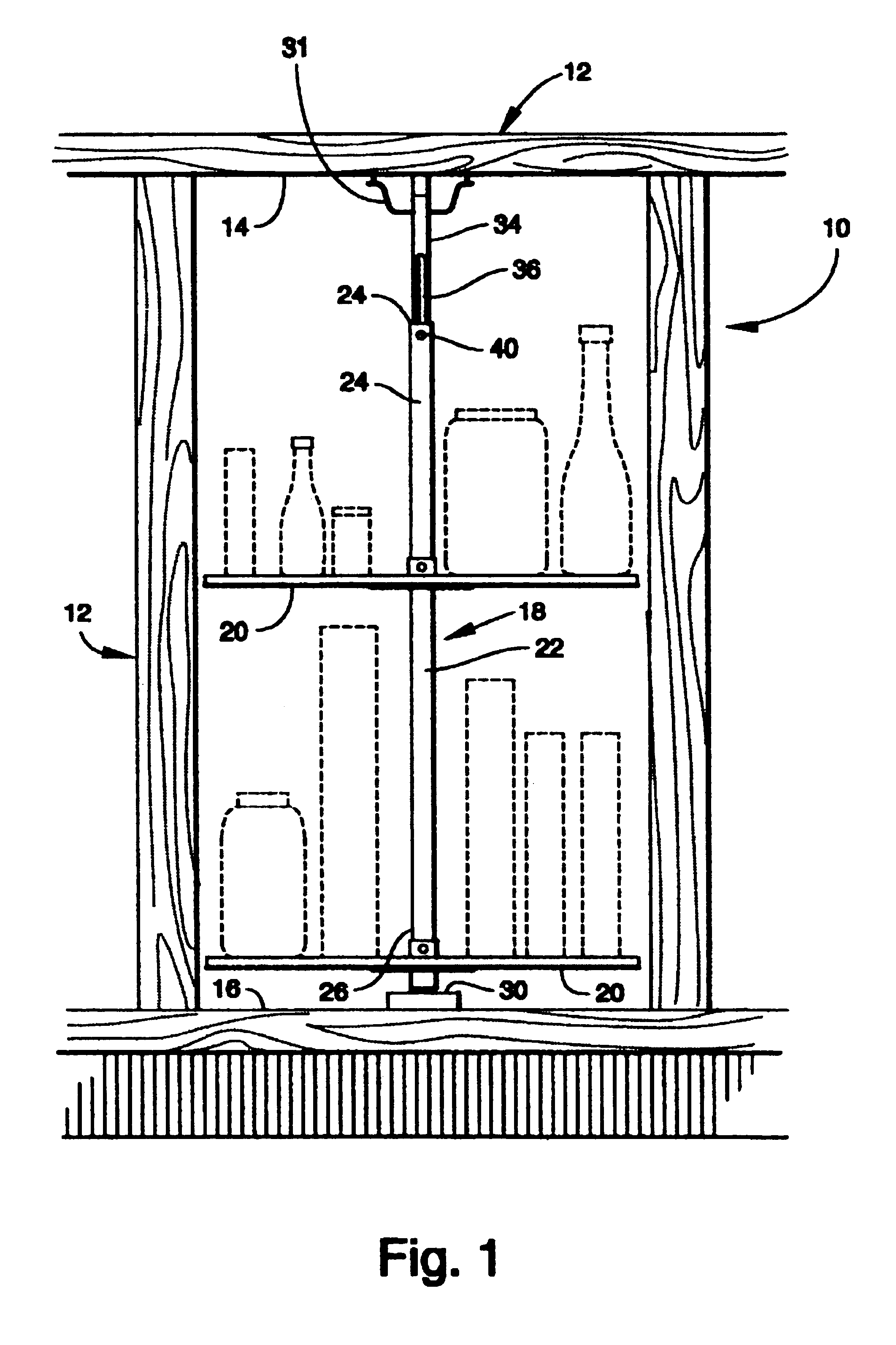
[0045]A rotational shelf assembly incorporating various features of the present invention is illustrated generally at 10 in FIG. 1. Shelf assembly 10 is designed to be installed in a cabinet 12 having installation surfaces comprising a ceiling surface or top 14 and a floor surface or bottom 16. However, it will be appreciated that the use of the assembly 10 is not confined to cabinet interiors and can be adapted for mounting in various storage areas having the necessary installation surfaces. Moreover, it will be understood that while assembly 10 has been titled a rotational shelf assembly, the term “shelf” as used herein encompasses various support structures for supporting items to be stored.

[0046]As shown in FIG. 1, assembly 10 comprises a support assembly 18 for rotatably mounting adjustable shelves 20. Support assembly 18 includes a first rotational support post 22 having upper and lower end portions 24, 26, the lower end portion 26 engagably supported by mounting bracket 30 an...


PUM


Abstract

A rotary shelf assembly mechanism has shelves mounted on a vertical post arrangement formed by a first lower post and a second upper post. The mechanism is connected to a cabinet by upper and lower mounting brackets interacting with the top and bottom of the cabinet to support the posts and shelves carried thereby. The mechanism is mounted in the corner of the cabinet. To fit the mechanism within the cabinet, a height adjustment device is formed by positioning the second upper post in the upper end of the first lower post for slidable movement therebetween. When securement of the two joined posts and mounted shelves is desired, the slidably movable second upper post is extended upwardly until it engages the upper mounting bracket mounted on the cabinet. An elongated recess in the second upper post aligns with an opening in the first lower post, and a threaded member extends into a casting positioned within the upper post. The threaded member is tightened to engage the casting and secure the two posts in a shelf-retaining and rotational mode. The height adjustment device enables quick and efficient installation of the mechanism within the cabinet interior. The mechanism also includes a one piece shelf construction having a post-securing section and a shelf-retaining pin.

Description

[0001]The present application is a continuation-in-part application of pending U.S. patent application Ser. No. 09 / 640,052 filed Aug. 17, 2000 now abandoned.BACKGROUND OF THE INVENTION[0002]1. Field of the Invention[0003]The present invention relates to a rotary shelf construction and assembly and to a shelf-supporting post height adjustment device to secure the post and carried shelves in a pre-selected relationship within the cabinet along with a shelf sustaining element to enable the speedy attachment and detachment of shelves to the post.[0004]2. Description of the Prior Art[0005]It has been common practice to provide corner kitchen cabinet shelves of a rotatable or “Lazy Susan” type. Such shelves are desirable because, without them, much cabinet space in the corner either above or below the kitchen counter is wasted due to the inaccessibility of items well back in the corner.[0006]One of the problems encountered with such a structure is the variance of non-uniform distances bet...

Claims


Application Information

Patent Timeline
IPC IPC(8): A47F5/02A47B49/00A47B57/26
CPCA47B49/004A47B57/26
Inventor DOMENIG, GEORGRAPIER, JAMES
Owner REV A SHELF
Why Eureka
Try Eureka