
Footgear with pressure relief zones

Inactive Publication Date: 2008-06-10
OSSUR HF
View PDF26 Cites 87 Cited by
  • Summary
  • Abstract
  • Description
  • Claims
  • Application Information

AI Technical Summary

Benefits of technology

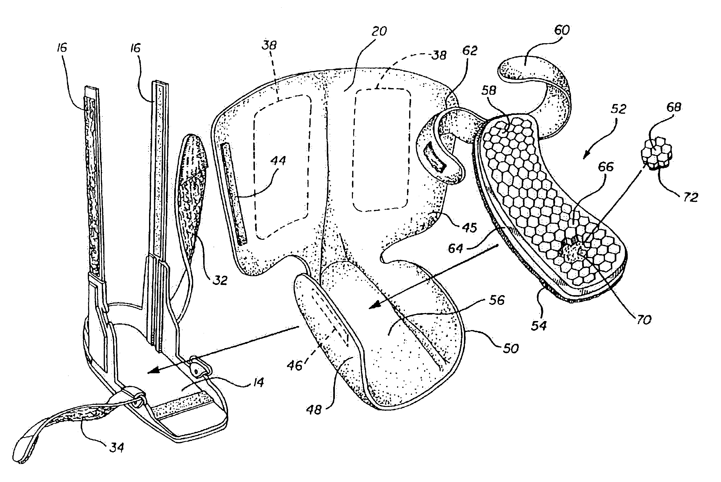
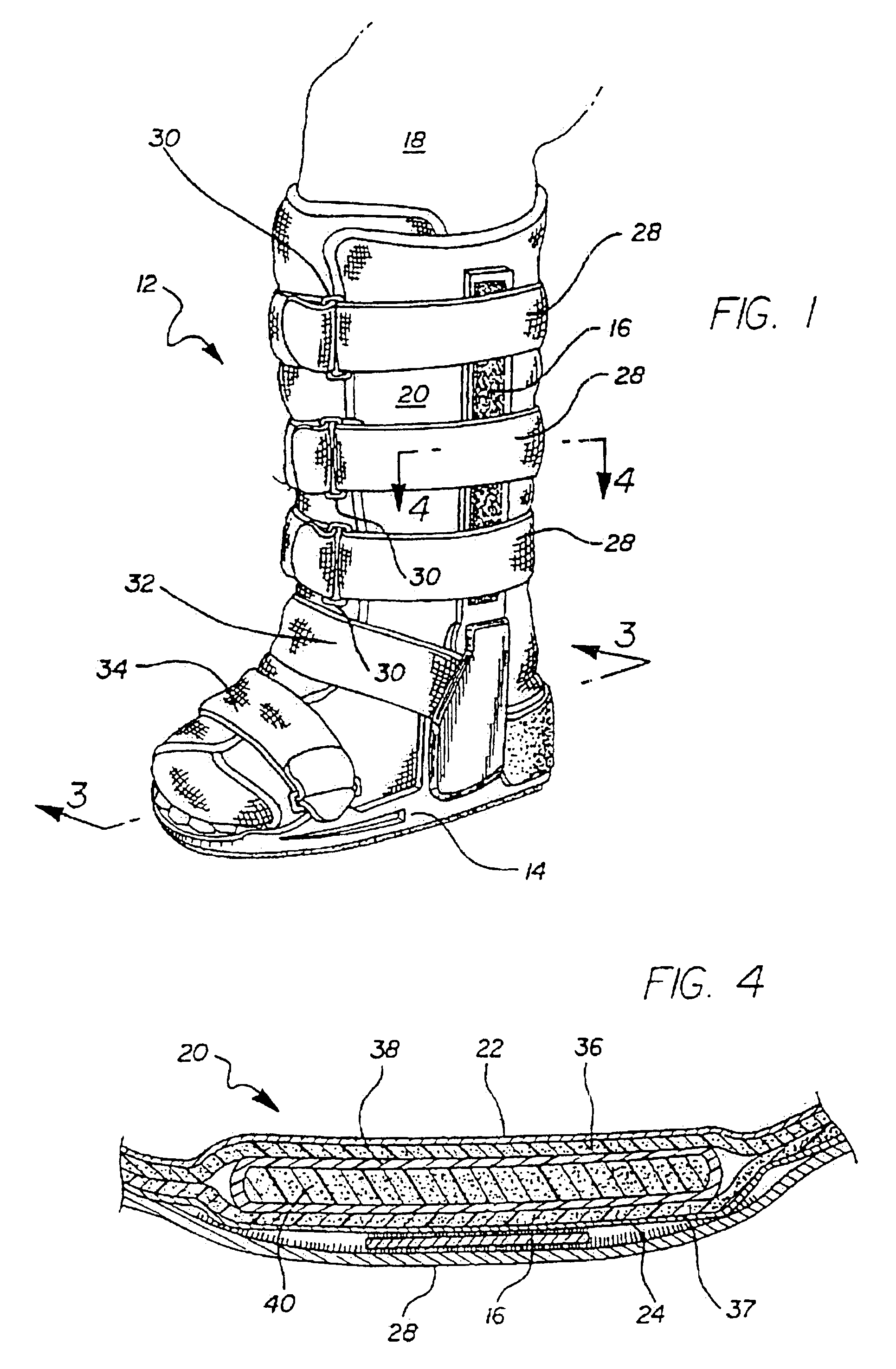
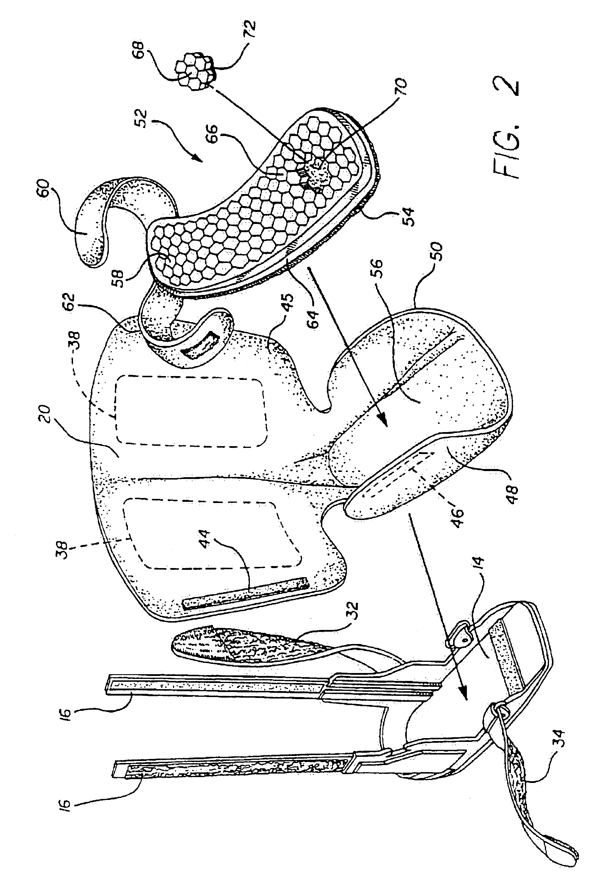
[0020]In accordance with one illustrative embodiment of the invention, a walker frame, including an outer sole and side struts may be provided with an air bladder mounted above the outer sole, and a special inner sole mounted above the bladder and made up of a large number of separate resilient sections removably secured to a flexible sheet to form a substantially flat surface for engagement by the foot. In areas where the foot is ulcerated or otherwise injured, sections of the inner sole are removed to provide pressure relief.
[0034]11. An edema patch may be provided for covering an open space left after a user has removed one or more mobile sections from the grid and for applying pressure to the afflicted zone of the foot, thereby preventing fluids from building up in the afflicted zone of the foot.

Problems solved by technology

A particular problem arises when it becomes necessary to provide uneven support across the outer surface of an appendage.
However, these approaches require replacement of the sole for each new patient, or for each new area of the original patient's foot which must be relieved.
Unfortunately, a number of problems arise when diabetes patients, who are prone to severe foot ulcers, attempt to use the Andrews device.
It is well known that diabetes patients are prone to foot ulcers.
With reduced sensation in the foot, the patient is unlikely to feel discomfort when the skin is subject to shear forces during walking, and consequently he or she does not properly adjust his or her gait.
Diabetes patients also experience other extreme difficulties with their feet.
Diabetic patients often undergo an unfortunate evolutionary pattern of anatomical deterioration.
However, the bone structure can quickly deteriorate.
From then on, the areas of the foot that can bear weight are abnormal, their locations are unpredictable, and custom foot accommodations will be required for the remainder of the person's ambulatory life.
The Andrews device does little to overcome these problems.
The Andrews fixed-location pad arrangement cannot provide pressure relief to damaged areas of the foot that are located anywhere except the four specific pad locations.
This makes Andrews inadequate for the majority of diabetes patients with damaged feet.
An additional drawback of the Andrews pad is that it lacks means to reduce shear forces on the skin of the foot that arise as the patient walks along.
Such shear forces can further damage existing ulcers, or create new ulcers.
This method requires a mechanism for heating, which may be inconvenient or impractical when applied to a comfortable sole.
Moreover, the elastomeric materials described in the Rudy patent typically may not provide the requisite comfort and cushioning generally required in a healing device.
However, the bladder members of the Grim device do not retain their shape except as restrained by the surface of the appendage itself and thus do not provide the desired semi-permanent areas of relief to an injured appendage.

Method used


Image

  • Footgear with pressure relief zones
  • Footgear with pressure relief zones
  • Footgear with pressure relief zones

Examples


Embodiment Construction

[0063]Referring more particularly to the drawings, FIG. 1 shows a walker 12 including a frame made up of an outer sole assembly 14 and two side struts 16 secured to the sole, and extending up on either side of the lower leg of the patient 18. Within the frame 14, 16, is a soft goods type support member 20 for enclosing the lower leg, ankle and most of the foot of the patient or user. As best shown in FIG. 4, the soft goods type body member 20 includes outer cloth material 22 and 24 separated by two layers of foam 36 and 37, which may be either foam rubber or foamed urethane, by way of examples. The soft goods type body member 20 may be held in position within the frame 14, 16, by pads of hook and loop type material on the inner surface of the struts 16, and by the straps 28 extending around the struts 16, through the D-rings 30 and then being folded back on the other portions of the straps, and held in adjustable positions by mating Velcro type hoop and loop areas on the surfaces of...


PUM


Abstract

Footgear with an inner sole (66) having a grid of removable resilient elements to permit removal of selected elements (68) to provide relief to ulcerated or injured areas of the foot. An air bladder (64) may underlie sole (66), preferably with additional cushioning material (40) within the air bladder. A walker (12) with a soft support (20) may be provided with the inner sole within the support. Some of the removal resilient elements may have a higher density or height than others. The footgear may include an adhesively-backed resilient pad (212) to provide additional support to a region. The footgear may include means for reducing shear stress on a bottom surface of the foot. An edema patch (240) may be provided for covering an open space (248) left after a user has removed a removable section from the grid. The edema patch applies pressure to the afflicted zone of the foot (250) preventing fluids from building up.

Description

RELATED PATENT APPLICATIONS[0001]This application is a continuation-in-part of U.S. patent application Ser. No. 08 / 017,818, which was filed Feb. 16, 1993 now U.S. Pat. No. 5,329,705. This invention is related to that disclosed in U.S. patent application Ser. No. 07 / 965,750, filed Oct. 23, 1992, (Docket No. 88-182), entitled “Orthopaedic Support and Method for Providing Semi-Permanent Relief Zones,” assigned to the assignee of this invention.FIELD OF THE INVENTION[0002]This invention relates to footgear having orthopaedic soles providing pressure relief areas for the feet.BACKGROUND OF THE INVENTION[0003]The problems solved by the present invention were discussed at length in the prior patent application cited above, and the background section of that application will therefore be repeated here.[0004]Support pads are used in a wide variety of applications to provide cushioned support to an injured or otherwise sensitive bodily appendage. Such pads have the dual purpose of (1) providi...

Claims


Application Information

Patent Timeline
IPC IPC(8): A43B7/14A43B13/38A43B7/20A43B13/40A43B17/02A43B17/03A61F5/00A61F5/01A61F5/37
CPCA43B1/0009A43B7/20A43B13/40A43B17/02A43B17/026A43B17/035A61F5/0111A61F5/012A43B7/1464A43B7/1463
Inventor GRIM, TRACY E.O'DONNELL, KEVINMONTAG, ERIC G.
Owner OSSUR HF
Learn More