Solid waste comminutor

a comminutor and waste technology, applied in the direction of shafts and bearings, cocoa, bearing components, etc., can solve the problems of affecting other critical components of the device, bearing failure, and scalding up the cutter stack, so as to reduce the stress on the shaft, maximum cutting efficiency, and fast installation

Inactive Publication Date: 2008-07-22
SULZER MANAGEMENT AG
View PDF33 Cites 0 Cited by
  • Summary
  • Abstract
  • Description
  • Claims
  • Application Information

AI Technical Summary

Benefits of technology

[0015]Further, in accordance with this invention the bearing-seal cartridges float within the housing to provide movement with shaft movement thereby reducing the stress on the shafts and bearings.
[0016]A quick exchange of the mechanical subassembly, which includes bearings, O-ring seals and cartridge housing itself can be effectuated. As a result of this modular assembly, an individual seal cartridge can be installed quickly without the need to disassemble the entire subassembly.
[0017]Another advantage of this technique is that the bearing-seal cartridge is identical for the top and bottom of the cutter stack. As a consequence, a deficiency in the prior art which used two different assemblies has been eliminated. The bearing-seal cartridge is an item which is pre-assembled and installed as received. Thus, there is no requirement that the individual items, the various races, bearings and the like be assembled at the job site. Rather, the cartridge is interchangeable as a unit and is inserted into the end housing.
[0018]Further, in accordance with this invention by retorquing of the cutter stack can be accomplished while the unit is still in-line and installed. It has ben demonstrated that in practice, the most common preventative maintenance function is re-torquing the cutter stack to maintain stack compression for maximum cutting efficiency.
[0019]Prior to this invention a loss of stack compressibility lead directly to premature seal and bearing failure, primarily of the bottom seal assembly. In accordance with this invention, the tightness of the seal assembly is independent of total stack height, since it is designed as a self contained unit no disassembly is required.
[0020]Another advantage of this invention is an early warning seal failure detection system which can be used to prevent premature bearing failure. The invention provides for a drain port and / or weep holes in the shafts that allow fluid permeating from the seal to escape to the exterior. This can thus be viewed by maintenance personnel during routine checks of the system.

Problems solved by technology

As can be appreciated, the environment of use is very harsh for the equipment and as such, routine maintenance is required in both a preventative sense and also to immediately repair break downs when they occur thus minimizing system down-time.
As a result, if there was a seal failure other critical components of the device were likely to be effected.
This failure of a seal could thus mean that bearings could fail and seize up the cutter stack.
In the context of a unit which is used in fluid waste treatment that down-time, in some cases as long as a day could have detrimental effects in the ability of a plant to process waste.
Such would require rerouting solid waste, shutting down a portion of the facility and otherwise result in an inefficient operation.
Consequently, tightening of the cutter stack, by compression, resulted in compression of the seals.
It has been recognized however, that under normal operating conditions the cutter thickness experiences wear and thus the overall thickness of the stack tends to reduce over time.
The result is an effective reduction in the overall stack height and the stack therefore tends to become loose.
As a consequence, initial compression of various seal components is lost and the seal faces tend to separate.
The result is leakage across the seal with the subsequent result of bearing failure.
Another deficiency in the prior art was the use of a labyrinth between the main fluid chamber and the seal faces.
Because such devices are used in applications which include a high grit content, the labyrinth tended to be a relatively high wear component.
As a consequence, seal components had to be removed to replace the labyrinth with the potential for seal damage upon reassembly.

Method used


Image

  • Solid waste comminutor
  • Solid waste comminutor
  • Solid waste comminutor

Examples


Embodiment Construction

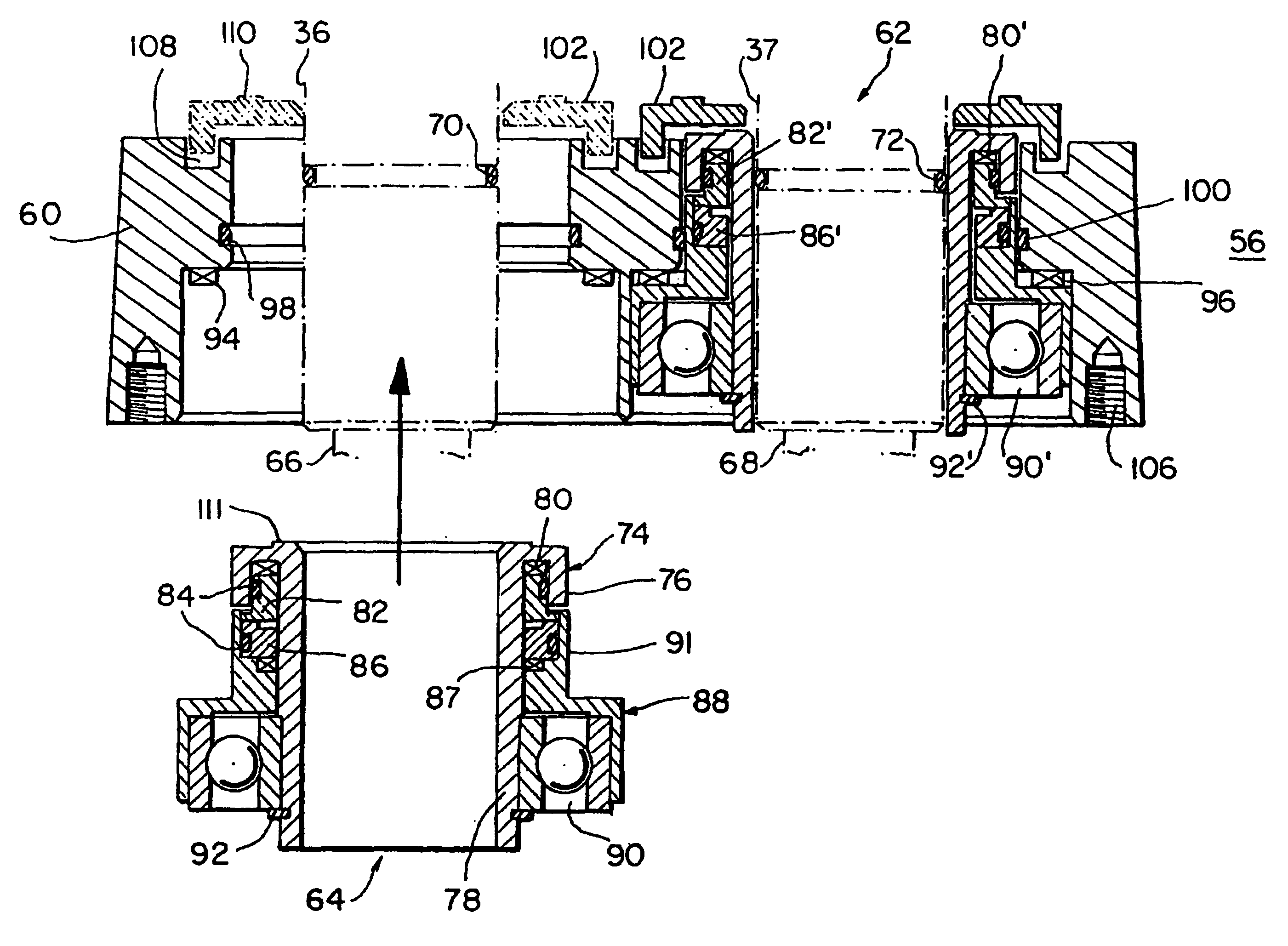
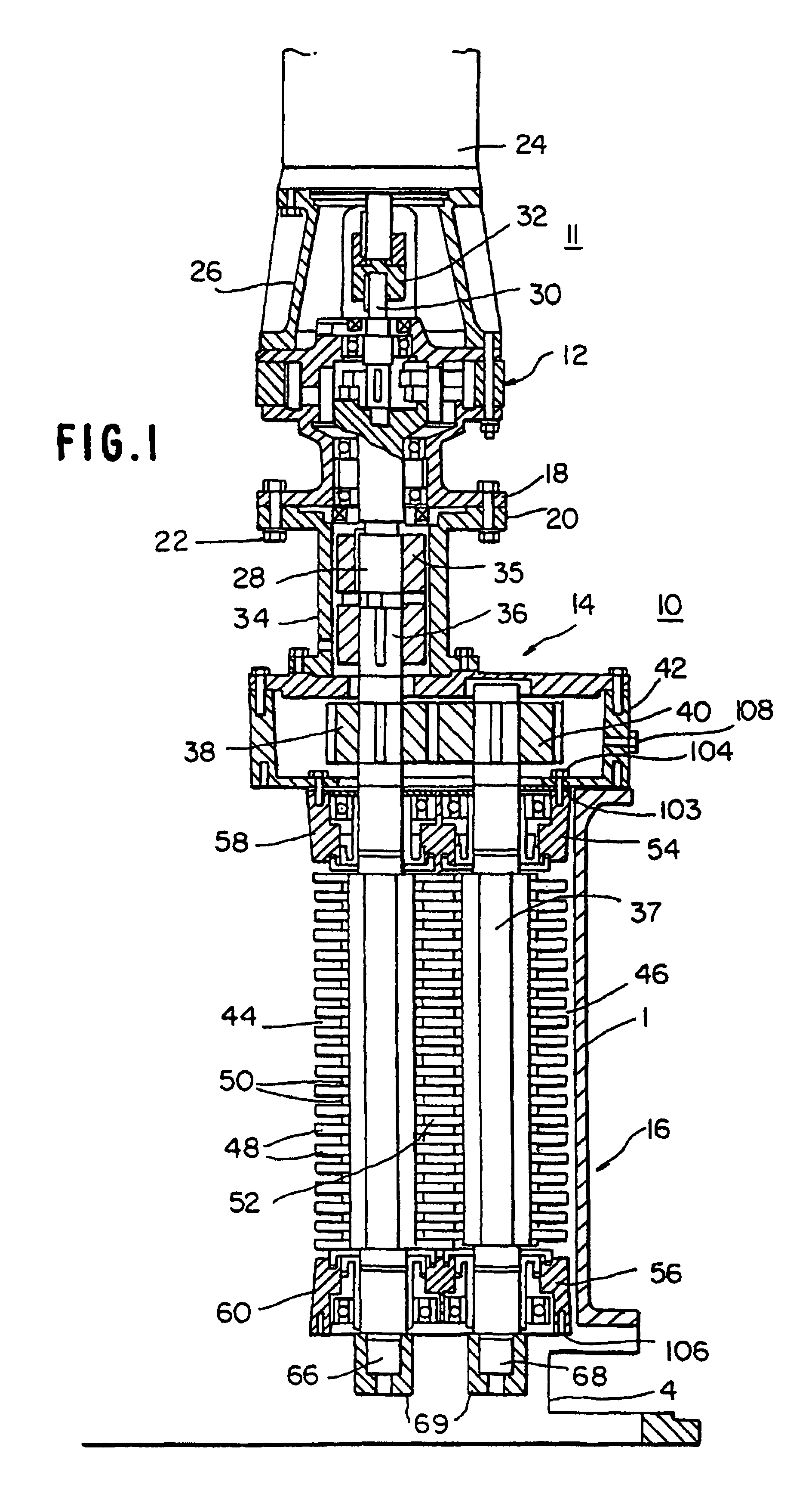
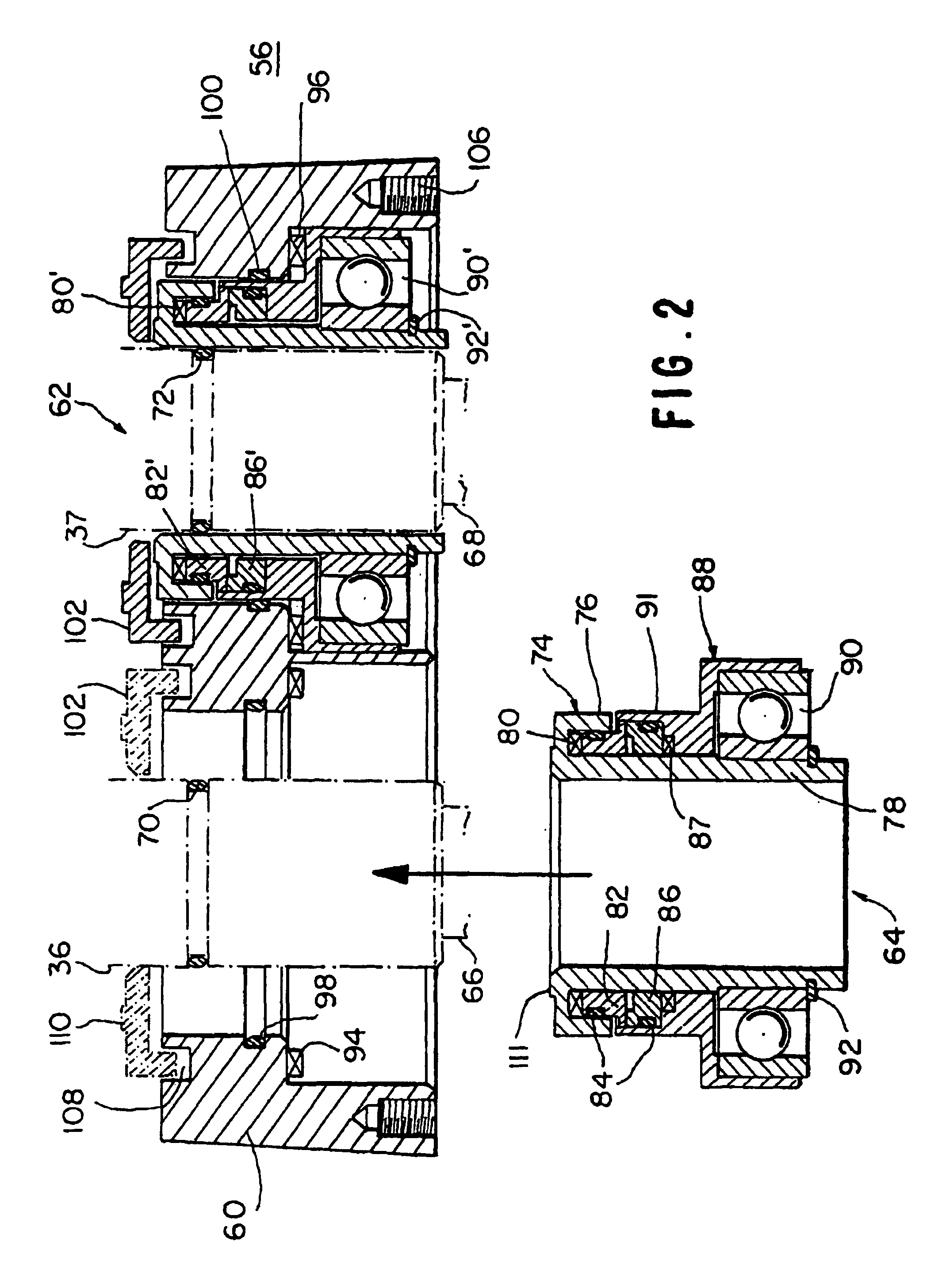
[0024]Referring now to FIG. 1, a cut-away side view of the overall system is depicted. In FIG. 1 the housing 1 has an inlet and outlet, not illustrated. At the bottom of the housing, a pair of access cut-outs 4 are provided to permit stack tightening, to be described herein, without disassembly of the device. The unit employs, three essential subsystems, which comprise a complete comminution apparatus 10. These are a drive subsystem 11 with a motor 24 and speed reducer 12, a gearing subsystem 14, and a cutting subsystem 16. The housing 26 for the speed reducer 12 is mounted to the gear and cutter system 14, 16 by a pair of conforming flange elements 18, 20, which are clamped together by means of bolts 22. The motor is topically an electric drive motor 24, the details of which need not be discussed in detail. It will be recognized by those skilled that a suitable motor and drive system can be employed consistent with the scope of intended use. The speed reducer is contained in a hous...


PUM


Abstract

A solid waste material comminuting system having aan electric motor for providing rotary motion, a pair of cutter stacks with cutter elements of one stack interleaved with cutter elements of the other, and gear means to transmit the rotary motion of the electric motor to counter-rotate cutter elements of one stack with cutter elements of the other. Each of the cutter stacks comprisecomprises a central shaft journaled for rotation and a seal-bearing assembly/module at each end of the central shafts. Each bearingassembly/module comprises an end housing, and a pair of insertable pre-assembled seal-bearing elements/assemblies mountable in each of said end housings. One seal-bearing element/assembly has a thru-hole for journaling a first shaft for rotation and a second seal-bearing element/assembly has a thru-hole for journaling a second shaft for rotation.

Description

BACKGROUND OF INVENTION[0001]This invention relates to a solid waste comminuting apparatus. Such devices have been established in the art and are now widely used in a variety of industrial applications, such as municipal waste treatment and industrial applications. Reference is made to U.S. Pat. No. 4,046,324, which discloses such a basic system that has achieved commercial success.[0002]By definition, communication is the reduction of particle size of solid waste material to minute particles. It is generally performed by shearing, shredding and crushing of the waste material. As set forth in the '324 patent, comminution occurs by utilizing a pair of counter-rotating intermeshed cutting members.[0003]The solid waste material is fed into the interface between cutting elements, typically utilizing a fluid carrier medium, and shearing action occurs because the two cutters overlap each other such that opposing forces of counter-rotation of the cutting elements on the different stacks ac...

Claims


Application Information

Patent Timeline
Patent Type & Authority Patents(United States)
IPC IPC(8): B02C7/04B02C18/00B02C18/18B02C18/14B02C18/16
CPCB02C18/0092B02C18/142F16C33/76B02C18/16B02C2018/188
Inventor CHAMBERS, SR., JOSEPH W.SABOL, ROBERT T.FENNESSY, CRAIG J.
Owner SULZER MANAGEMENT AG
Why Eureka
Try Eureka