Multilumen catheter assembly and methods for making and inserting the same

a multi-lumen catheter and assembly technology, applied in the direction of multi-lumen catheters, catheters, suction devices, etc., can solve the problems of increasing the attendant risks of catheterization procedures, affecting the safety of patients, and unable to achieve the effect of a single techniqu

Inactive Publication Date: 2009-09-08
MEDICAL COMPONENTS INC
View PDF145 Cites 8 Cited by
  • Summary
  • Abstract
  • Description
  • Claims
  • Application Information

AI Technical Summary

Problems solved by technology

However, this technique is only possible in cases where the catheter is of a relatively small diameter, made of a stiff material and not significantly larger than the guide wire, for example, for insertion of small diameter dual lumen catheters.
The Tesio double catheter assembly, while comfortable for the patient, due to its soft durometer, and very effective for hemodialysis, typically requires multiple procedures and incisions for insertion and / or for tunneling, which increase the attendant risks of the catheterization procedure.
Further, in the case of side-by-side placement of two catheter tubes through a single insertion site in a vessel, while minimizing the number of procedures, can present a potential for leakage between the catheter tubes at the point where the catheter tubes pass into the vessel.
Further, the softer durometer of such catheters, which are typically made of a silicone or a similar material, reduces the risk of vessel wall damage.
Further, since the retaining sleeve is located outside the vessel when in place to provide the self-retaining feature, at the point of entry into the vessel, the catheters are side-by-side in the manner of a standard Tesio catheter, and there still remains the potential risk of blood leakage between the catheters at the vessel site.

Method used


Image

  • Multilumen catheter assembly and methods for making and inserting the same
  • Multilumen catheter assembly and methods for making and inserting the same
  • Multilumen catheter assembly and methods for making and inserting the same

Examples


Embodiment Construction

[0032]Certain terminology is used herein for convenience only and is not to be taken as a limitation on the present invention. The words “right,”“left,”“outwardly” and “inwardly” designate directions in the drawings to which reference is made. The words “proximal” and “distal” refer to directions away from and closer to, respectively, the insertion tips of the first and second catheters in the multiple catheter assembly according to the present invention. The terminology includes the words above specifically mentioned, derivatives thereof, and words of similar import.

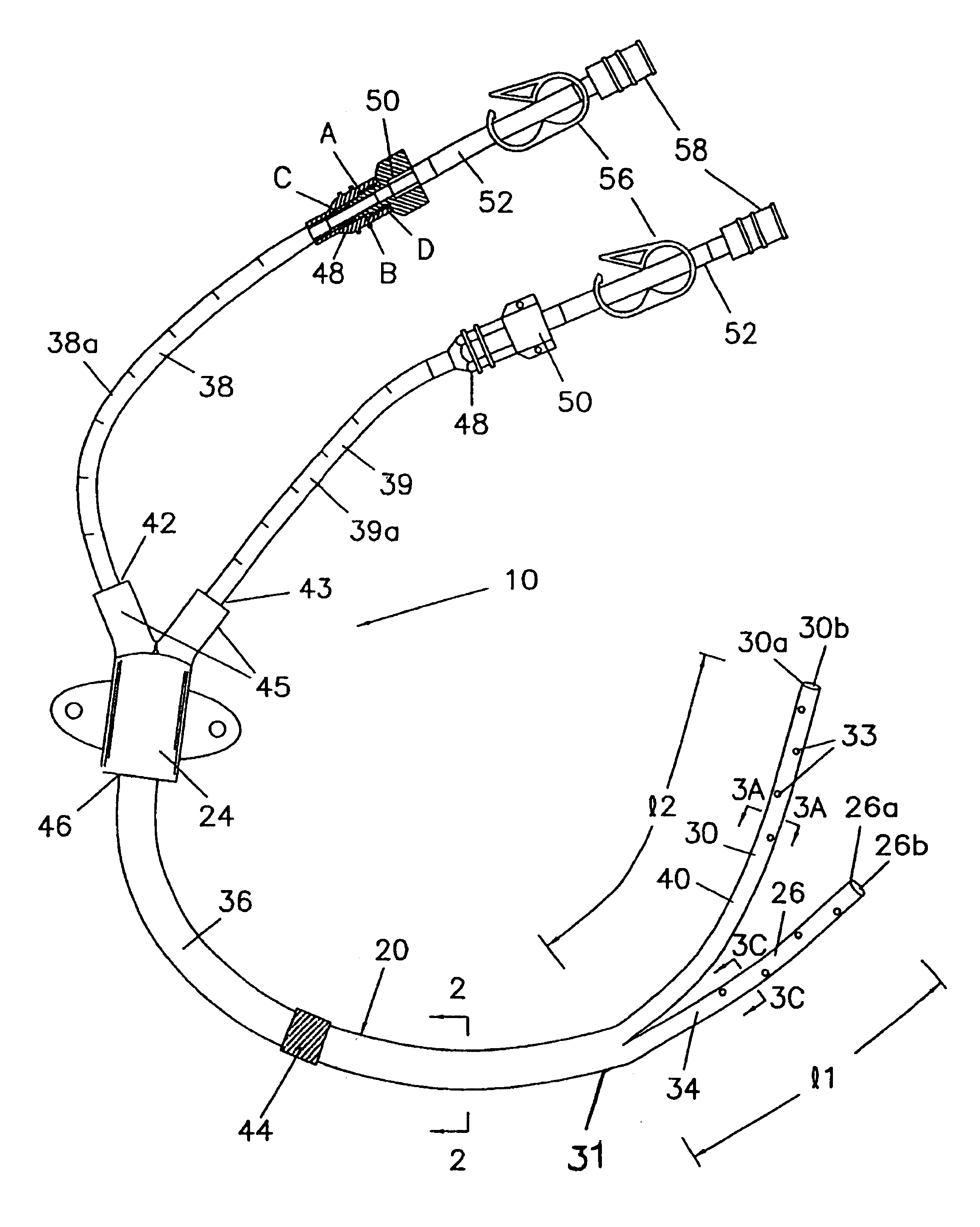
[0033]The following describes preferred embodiments of the invention. However, it should be understood, based on this disclosure, that the invention is not limited by the preferred embodiments described herein. Referring now: to the drawings in detail, there are shown in FIG. 1, a preferred embodiment of a multilumen catheter assembly generally indicated as 10, according to the invention. The multilumen catheter assembl...


PUM


Abstract

A multilumen catheter assembly and methods for making and inserting the same are provided. The catheter assembly includes a unitary catheter and at least two distal end tubes which extend distally from the unitary catheter. The at least two lumens in the unitary catheter are in fluid communication with passageways through the distal end tubes. The catheter assembly may be made by extruding a unitary catheter tube having internal longitudinally extending lumens, then splitting the tube on its distal end portion to form distal end tubes. The tubes are then ground and polished to form a smooth surface on the exterior of the tubes. The catheter assembly may also be made by forming an outer layer on at least two longitudinally extending catheters while leaving two distally extending portions of the tubes outside the outer layer to form the distal end tubes. The multilumen catheter assembly may be inserted in a patient for acute and chronic catheterization and subcutaneously tunneled and inserted using a single insertion procedure while leaving the distal end tubes within the vessel capable of free movement and sealing the insertion site into an area to be catheterized.

Description

BACKGROUND OF THE INVENTION[0001]Catheters for the introduction or removal of fluids may be located in various venous locations and cavities throughout the body for the introduction or removal of fluids. Such catheterization may be performed by using a single catheter having multiple lumens. A typical example of a multiple lumen catheter is a dual lumen catheter in which one lumen introduces fluids and one lumen removes fluids. Catheterization may also be performed by using separate, single lumen catheters inserted through two different incisions into an area to be catheterized. Such multiple catheter assemblies are known as Tesio catheters. Procedures are also known as described in U.S. Pat. No. 5,624,413 for inserting two wholly independent single lumen catheters into a vessel through a single insertion site.[0002]Generally, to insert any catheter in a blood vessel, the vessel is identified by aspiration with a long hollow needle in accordance with the Seldinger technique. When bl...

Claims


Application Information

Patent Timeline
Patent Type & Authority Patents(United States)
IPC IPC(8): A61M27/00A61M25/00
CPCA61M25/0009A61M25/0029A61M25/0068A61M25/007A61M25/008A61M2025/0031A61M2025/0037A61M2025/0081
Inventor SCHWEIKERT, TIMOTHY M.MADISON, ANTHONY J.SCHON, DONALD A.
Owner MEDICAL COMPONENTS INC
Why Eureka
Try Eureka