Endocardial mapping system

a mapping system and endocardial technology, applied in the field of endocardial mapping system, can solve the problems of inability to accurately resolve the location of ectopic tissue masses, the two-dimensional maps of the electrical potentials at the endocardial surface generated by these traditional processes suffer many defects, and the resolution of traditional systems is limited

Inactive Publication Date: 2010-05-11
ST JUDE MEDICAL ATRIAL FIBRILLATION DIV
View PDF100 Cites 59 Cited by
  • Summary
  • Abstract
  • Description
  • Claims
  • Application Information

AI Technical Summary

Problems solved by technology

The two-dimensional maps of the electrical potentials at the endocardial surface generated by these traditional processes suffer many defects.
Traditional systems have been limited in resolution by the number of electrodes used.
The small number of signals from the endocardial wall will result in the inability to accurately resolve the location of ectopic tissue masses.
Such interpolated two-dimensional maps have significant deficiencies.
First, if a localized ectopic focus is between two electrode views such a map will at best show the ectopic focus overlaying both electrodes and all points in between and at worst will not see it at all.
Second, the two dimensional map, since it contains no chamber geometry information, cannot indicate precisely where in the three dimensional volume of the heat chamber an electrical signal is located.
The inability to accurately characterize the size and location of ectopic tissue frustrates the delivery of certain therapies such as “ablation”.

Method used


Image

  • Endocardial mapping system
  • Endocardial mapping system
  • Endocardial mapping system

Examples


Embodiment Construction

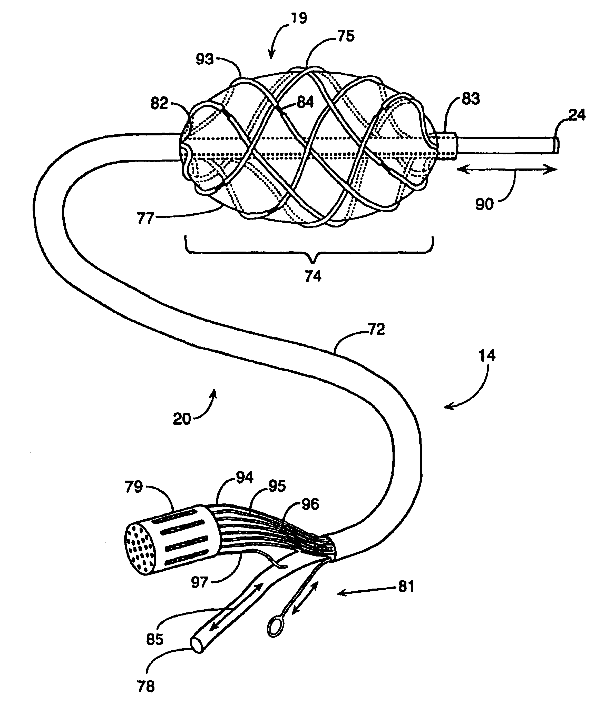
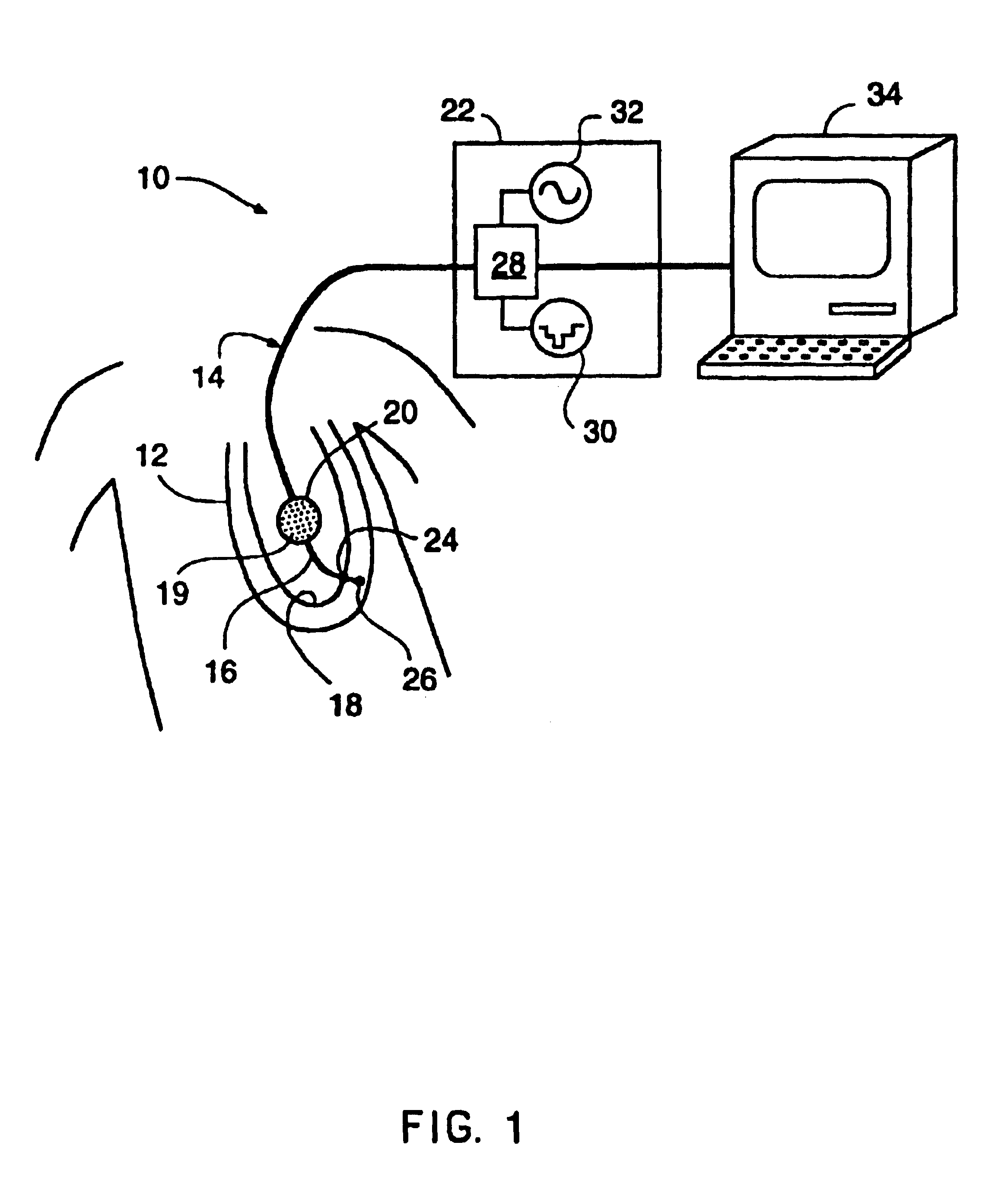
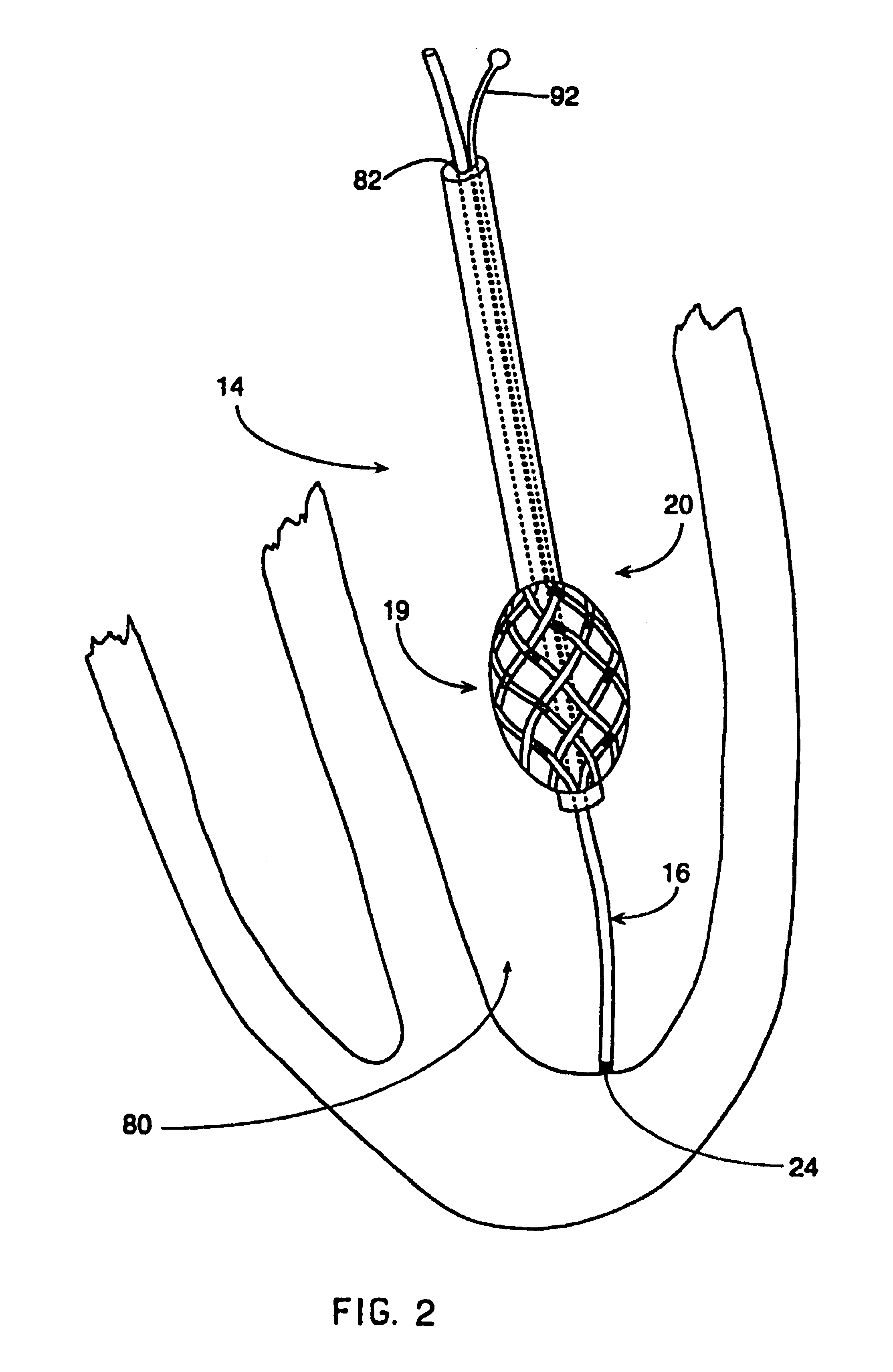
[0023]In general, the system of the present invention is used for mapping the electrical activity of the interior surface of a heart chamber 80. The mapping catheter assembly 14 includes a flexible lead body 72 connected to a deformable distal lead body 74. The deformable distal lead body 74 can be formed into a stable space filling geometric shape after introduction into the heart cavity 80. This deformable distal lead body 74 includes an electrode array 19 defining a number of electrode sites. The mapping catheter assembly 14 also includes a reference electrode preferably placed on a reference catheter 16 which passes through a central lumen 82 formed in the flexible lead body 72 and the distal lead body 74. The reference catheter assembly 16 has a distal tip electrode assembly 24 which may be used to probe the heart wall. This distal contact electrode assembly 24 provides a surface electrical reference for calibration. The physical length of the reference catheter 16 taken with t...


PUM


Abstract

A system for mapping electrical activity of a patient's heart includes a set of electrodes spaced from the heart wall and a set of electrodes in contact with the heart wall. Voltage measurements from the electrodes are used to generate three-dimensional and two-dimensional maps of the electrical activity of the heart.

Description

CROSS-REFERENCE TO RELATED APPLICATIONS<?insert-end id="INS-S-00001" ?> [0001]This application is a continuation-in-part of U.S. nonprovisional application Ser. No. 08 / 376,067, filed Jan. 20, 1995, now U.S. Pat. No. 5,553,611, which is a continuation of U.S. nonprovisional application Ser. No. 08 / 178,128, filed Jan. 6, 1994, now abandoned. This application is a reissue of U.S. nonprovisional application Ser. No. 08 / 387,832, filed May 26, 1995, now U.S. Pat. No. 6,240,307, which is a 371 of PCT / US1993 / 09015, filed Sep. 23, 1993, which is a continuation-in-part of U.S. nonprovisional application Ser. No. 07 / 950,448, filed Sep. 23, 1992, now U.S. Pat. No. 5,297,549 and U.S. nonprovisional application Ser. No. 07 / 949,690, filed Sep. 23, 1992, now U.S. Pat. No. 5,311,866.<?insert-end id="INS-S-00002" ?>[0002]Applicants have filed a child application of the present reissue of U.S. Pat. No. 6,240,307. The child application is application Ser. No. 10 / 955,894.TECHNICAL FIELD[0003...

Claims


Application Information

Patent Timeline
Patent Type & Authority Patents(United States)
IPC IPC(8): A61B5/0402A61B5/308A61B18/14
CPCA61B5/0538A61B5/6853A61B5/6858A61B18/1492A61B2560/045A61B2562/043A61B2562/046A61B5/282A61B5/283A61B5/287A61B5/30
Inventor BEATTY, GRAYDON ERNESTKAGAN, JONATHANBUDD, JEFFREY ROBERT
Owner ST JUDE MEDICAL ATRIAL FIBRILLATION DIV
Why Eureka
Try Eureka