Visual calibration target set method

a technology of target set and calibration method, which is applied in the field of calibration of computer monitor displays, can solve the problems of ineffective reliable tone calibration of crt displays, limited methods that can verify the actual tonality, etc., and achieve high-quality display calibration and high quality

Inactive Publication Date: 2011-02-01
HOLMES JOSEPH
View PDF6 Cites 14 Cited by
  • Summary
  • Abstract
  • Description
  • Claims
  • Application Information

AI Technical Summary

Benefits of technology

[0039]Fifth, the above features of the current invention make the use of a visual calibration method based on most or all of the above features a practical, realistic, economical, and highly effective solution to high-quality display calibration. Even the sum of all prior art does not teach a comp

Problems solved by technology

The prior art methods provide only limited ability to verify the actual tonality of a display and its conformity to a standard tone curve, because the methods of the prior art do not reveal the tonality of each relevant subsection of the tone curve.
Also, some prior art

Method used


Image

  • Visual calibration target set method
  • Visual calibration target set method
  • Visual calibration target set method

Examples


second embodiment

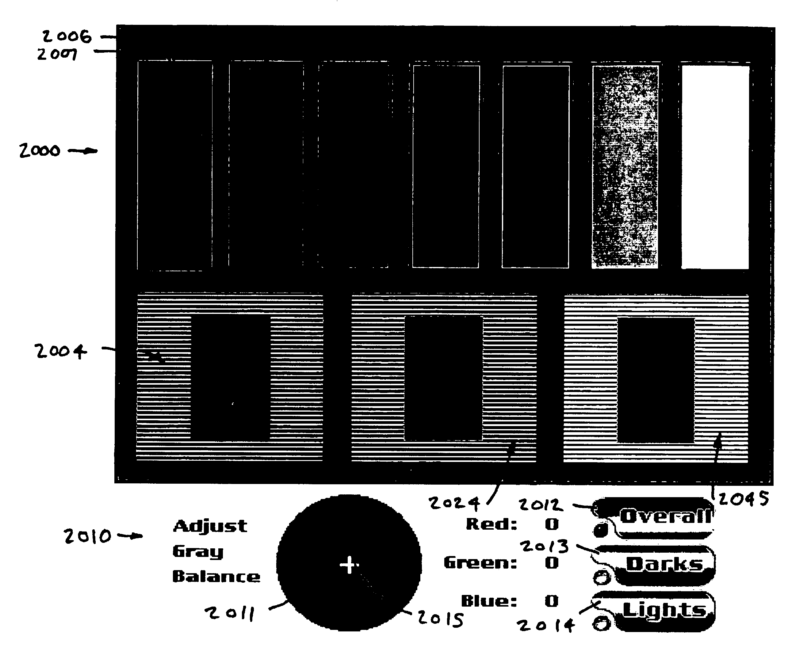
[0211]A second preferred embodiment of the gray balance features of the present invention is referred to as the Gray Balance Method Two, Increased Precision target 2300 (see FIGS. 23, 24 and 25). This target is optimized for displays that do not suffer seriously from an inability to display individual white pixels surrounded in the same horizontal row by black pixels with predictable luminosity, which may be much the same as that luminosity produced when the same white pixel is surrounded by white pixels. Flat panel displays may be inherently more capable of this than are CRTs. This second embodiment is also useful for increased gray balance precision on CRTs, despite their potential inability to display pixels that are unaffected by the surrounding pixels within a given horizontal row of pixels (scan line).

[0212]The light or quartertone sub-target 2304 comprises a light or quartertone solid 2307 adjacent to a blended region 2306 having a mixture of midtone pixels and light (prefera...

first embodiment

[0219]Once the midtone sub-target 2303 has been used to match the color of its gray midtone solid 2309 to the hue and chroma of the white, the combination of white and midtone colors used in sub-target 2304 then makes it possible to achieve enhanced accuracy for the light quartertone solid 2307 gray balancing. The values chosen for the quartertone sub target 2045 of the Gray Balance Method Two (FIG. 9) allow the quartertone sub-target 2045 of FIG. 9 to be to make quartertone adjustments prior to accurate adjustment of the midtone sub-target 2024, but these chosen values also assume relative freedom from color crossovers in the light end of the uncalibrated tone scale of the display. This freedom from crossovers is typical of CRTs but less typical of flat panel displays, which usually do suffer considerable color crossovers in the lighter portion of their uncalibrated tone scale.

[0220]Note that the Gray Balance Method Two and Gray Balance Method One targets of the present invention c...


PUM


Abstract

A novel process of visual calibration of a computer display or the like in volves adjusting the appearance and relative appearance of targets and su targets displayed on the display. An objective method is provided for determining the precisely optimal brightness setting for CRT displays, which method is also applicable to the setting of the “Black Level” control on some FPDs. A precise method is provided to visually determine conformity of a display's tonality to a given standard tone curve, for example a gamma 1.8 curve, which is embodied in one of the preferred calibration target sets. The need to sense and therefore be able to control and to verify the correct gray balance of the entire tone scale of the display is met. The problem of verifying the similarity of the tone curve in the display profile and that of the actual calibration is solved. By converting a preferred RGB gamma target into CIE Lab image data through an ideal display profile of the correct gamma, a new kind of target is taught.

Description

CROSS REFERENCE TO RELATED APPLICATIONS[0001]This application claims the benefit of U.S. Provisional Application No. 60 / 185,969, filed Mar. 1, 2000.FEDERALLY SPONSORED RESEARCH OR DEVELOPMENT[0002]Not applicable.CD-R APPENDIX[0003]This application includes a one-disk CD-R Appendix, the full contents of which are incorporated by reference herein. The disk contains the following files, listed by file name, creation date and file size in bytes: “ColorBlind Video Startup” created Jun. 22, 1999, 100K; “ColorBlind_Video_Startup.exe” created Sep. 16, 1999, 160K; “Complete_Text.txt” created Feb. 22, 2001, 40K; “Contents_of_CD.txt” created Feb. 22, 2001, 4K; “Lab Color Space Profile” created Aug. 4, 1997, 7K; “Prove it!” created Aug. 27, 1999, 4,116K; “Prove it! Installer” created Jul. 20, 1999, 2,251K; “Prove it_Beta.exe” created Jul. 16, 1999, 11,555K; and “Prove_it_Setup.exe” created Nov. 18, 1999, 7,432K.FIELD OF THE INVENTION[0004]This invention relates to the calibration of computer mo...

Claims


Application Information

Patent Timeline
IPC IPC(8): H04N17/00H04N17/02H04N1/60H04N17/04
CPCH04N1/6033H04N17/02H04N17/04
Inventor HOLMES, JOSEPH
Owner HOLMES JOSEPH
Why Eureka
Try Eureka