Abnormality detection and surveillance system

a technology applied in the field of abnormality detection and surveillance system, can solve the problems of poor resolution, complex viewing, and less personnel to adequately supervise monitors, and achieve the effect of reducing the number of tv monitors and guards

Inactive Publication Date: 2012-01-31
PROPHET PRODN
View PDF16 Cites 24 Cited by
  • Summary
  • Abstract
  • Description
  • Claims
  • Application Information

AI Technical Summary

Benefits of technology

[0012]It is another object of this invention to provide a surveillance system which can cull out real-time events which indicate criminal intent using a weapon, by resolving the low temperature of the weapon relative to the higher body temperature and by recognizing the stances taken by the person with the weapon.
[0013]It is yet another object of this invention to provide a surveillance system which eliminates or reduces the number of TV monitors and guards presently required to identify abnormal events, as this system will perform this function in near real time.

Problems solved by technology

These improvements flow fewer personnel to adequately supervise the monitors to cover the larger protected area.
These improvements, however, still require the constant attention of at least one person.
The above described multiple-image / single screen systems suffered from poor resolution and complex viewing.
Eventually, it was recognized that human personnel could not reliably monitor the “real-time” images from one or several cameras for long “watch” periods of time.
As discussed above, it is the human link which lowers the overall reliability of the entire surveillance system.
The surveillance system disclosed in U.S. Pat. No. 4,737,847 does remove some of the monitoring responsibility otherwise placed on human personnel; however, such a system can only determine an intruder's “intent” by his presence relative to particular zones.

Method used


Image

  • Abnormality detection and surveillance system
  • Abnormality detection and surveillance system
  • Abnormality detection and surveillance system

Examples


Embodiment Construction

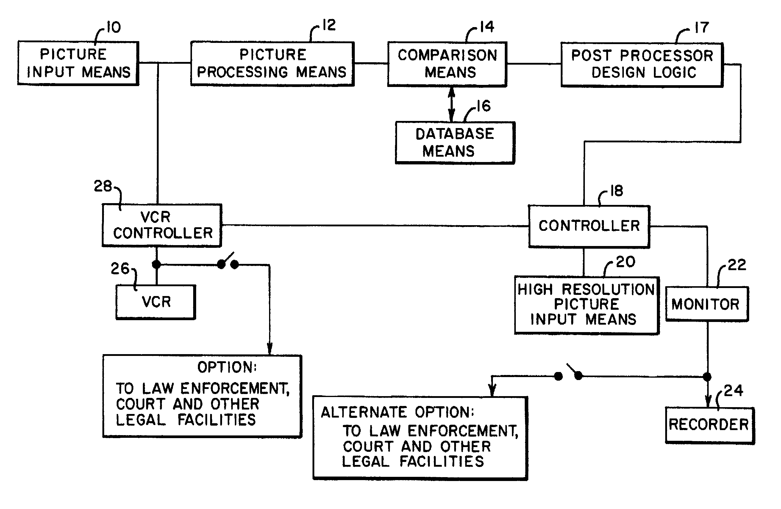
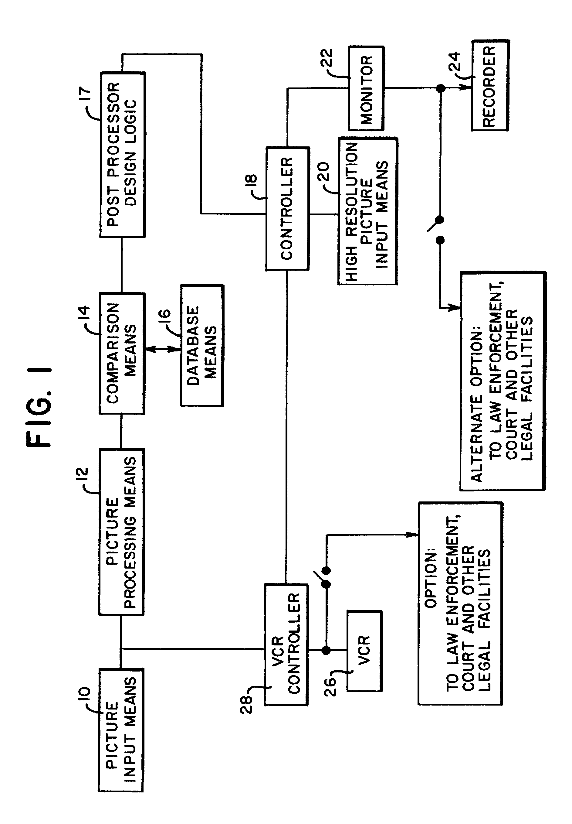
[0039]Referring to FIG. 1, the picture input means 10, may be any conventional electronic picture pickup device operational within the infrared or visual spectrum (or both) including a vidicon and a CCD / TV camera of moderate resolution, e.g., a camera about 1½ inches in length and about 1 inch in diameter, weighing about 3 ounces, including for particular deployment a zoom lens attachment. This device is intended to operate continuously and translate the field of view (“real”) images within a first observation area into conventional video electronic signals.

[0040]Alternatively, a high rate camera / recorder, up to 300 frames / see (similar to those made by NAC Visual Systems of Woodland Hills, Calif., SONY and others) may be used as the picture input means 10. This would enable the detection of even the very rapid movement of body parts that are indicative of criminal intent, and their recording, as hereinbelow described. The more commonly used camera operates at 30 frames per second an...


PUM


Abstract

A surveillance system having at least one primary video camera for translating real images of a zone into electronic video signals at a first level of resolution. The system includes means for sampling movements of an individual or individuals located within the zone from the video signal output from at least one video camera. Video signals of sampled movements of the individual is electronically compared with known characteristics of movements which are indicative of individuals having a criminal intent. The level of criminal intent of the individual or individuals is then determined and an appropriate alarm signal is produced.

Description

FIELD OF THE INVENTION[0001]This invention generally relates to surveillance systems, and more particularly, to trainable surveillance systems which detect and respond to specific abnormal video and audio input signals.BACKGROUND OF THE INVENTION[0002]Today's surveillance systems vary in complexity, efficiency and accuracy. Earlier surveillance systems use several closed circuit cameras, each connected to a devoted monitor. This type of system works sufficiently well for low-coverage sites, i.e., areas requiring up to perhaps six cameras. In such a system, a single person could scan the six monitors, in “real” time, and effectively monitor the entire (albeit small) protected area, offering a relatively high level of readiness to respond to an abnormal act or situation observed within the protected area. In this simplest of surveillance systems, it is left to the discretion of security personnel to determine, first, if there is any abnormal event in progress within the protected area...

Claims


Application Information

Patent Timeline
Patent Type & Authority Patents(United States)
IPC IPC(8): H04N7/18G08B13/194H04N5/76
CPCG08B13/19602G08B13/19608G08B13/19613G08B13/19643G08B13/19697H04N5/76H04N7/188
Inventor AVIV, DAVID, G.
Owner PROPHET PRODN
Why Eureka
Try Eureka