Vehicular lamp

a technology of a vehicle and a lamp body is applied in the field of vehicles, which can solve the problems of increasing the size of the control circuit portion, limiting the application of conventional structures, and limiting the space left for certain amount of space, so as to achieve a more compact overall lamp, high heat loss, and high heat loss

Inactive Publication Date: 2010-04-20
KOITO MFG CO LTD
View PDF2 Cites 6 Cited by
  • Summary
  • Abstract
  • Description
  • Claims
  • Application Information

AI Technical Summary

Benefits of technology

[0007]One or more embodiments of the present invention provide a compact vehicular lamp that achieves downsizing of a control circuit portion, and downsizing of the overall unit through an adjacent arrangement with an LED light source assembly portion.
[0009]According to the above configuration, the LED light source and the lighting circuit portion are both structured using bus bars with high heat loss. Therefore, the LED light source and the lighting circuit portion can achieve an adjacent arrangement. In addition, by using the bus bars with high heat loss, dispersion resistors to compensate for heat generation can be eliminated or reduced in number. Therefore, the lighting circuit portion itself can be downsized. As a consequence, a unit structured by the LED light source and the lighting circuit portion can be downsized, thereby achieving a more compact lamp overall.
[0010]In one or more embodiments of the present invention, the bus bar to which the LED light source is fixed and the bus bar to which the circuit element is fixed are formed as a combined bus bar. According to such a configuration, the bus bars of the LED light source and the lighting circuit portion are combined, and following the assembly of electronic components, are subjected to bending. The unit can thus be downsized, thereby achieving a more compact lamp overall.
[0011]In one or more embodiments of the present invention, the bus bar to which the LED light source is fixed and the bus bar to which the circuit element is fixed are respectively held on separate boards, and the board holding the bus bar to which the circuit element is fixed is bendably formed on the back of the board holding the bus bar to which the LED light source is fixed. According to such a configuration, after the bus bars of the LED light source and the lighting circuit portion are separately formed, both are bendably joined. Likewise, the unit can thus be downsized, thereby achieving a more compact lamp overall.
[0012]In one or more embodiments of the present invention, the board is structured by the lamp body, and the bus bar is supported by both sides of the lamp body. According to such a configuration, it is possible to accurately fix a bus bar of the LED light source and a bus bar of the lighting circuit portion that have been formed and processed into complex shapes such as a stepped configuration. Accordingly, the unit can be efficiently accommodated regardless of whether the front cover has a curved shape, and thus achieve a more compact lamp overall.
[0013]According to one or more embodiments of the present invention, the LED light source and the lighting circuit portion are both structured using bus bars with high heat loss. Therefore, the LED light source and the lighting circuit portion can achieve an adjacent arrangement. In addition, by using the bus bars with high heat loss, dispersion resistors to compensate for heat generation can be eliminated. Therefore, the lighting circuit portion itself can be downsized. As a consequence, a unit structured by the LED light source and the lighting circuit portion can be downsized, thereby achieving a more compact lamp overall.

Problems solved by technology

However, a certain amount of space must be left due to the heat emitted by the printed circuit board 8, and the arrangement can only be made so compact using the conventional structure.
As a consequence, as more resistors are used, the size of the control circuit portion increases.

Method used


Image

  • Vehicular lamp
  • Vehicular lamp
  • Vehicular lamp

Examples


Embodiment Construction

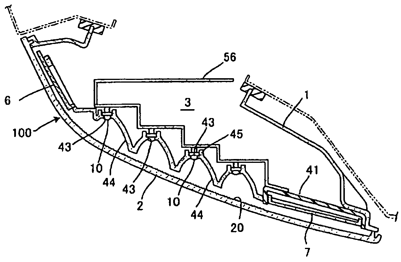
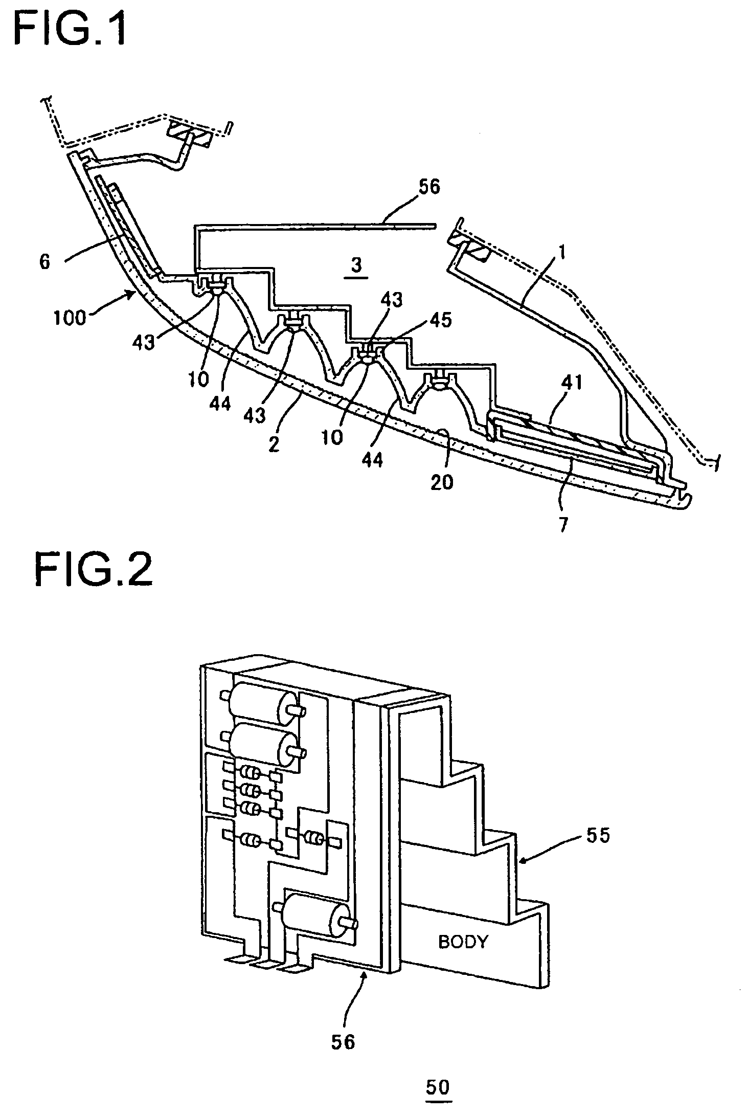
[0030]FIG. 1 is a horizontal cross-sectional view showing a structure of a vehicular lamp according to one or more embodiments of the present invention. Here, a tail and stop lamp, i.e., a marker lamp, will be used in the following description as an example of a vehicular lamp according to one or more embodiments of the present invention.

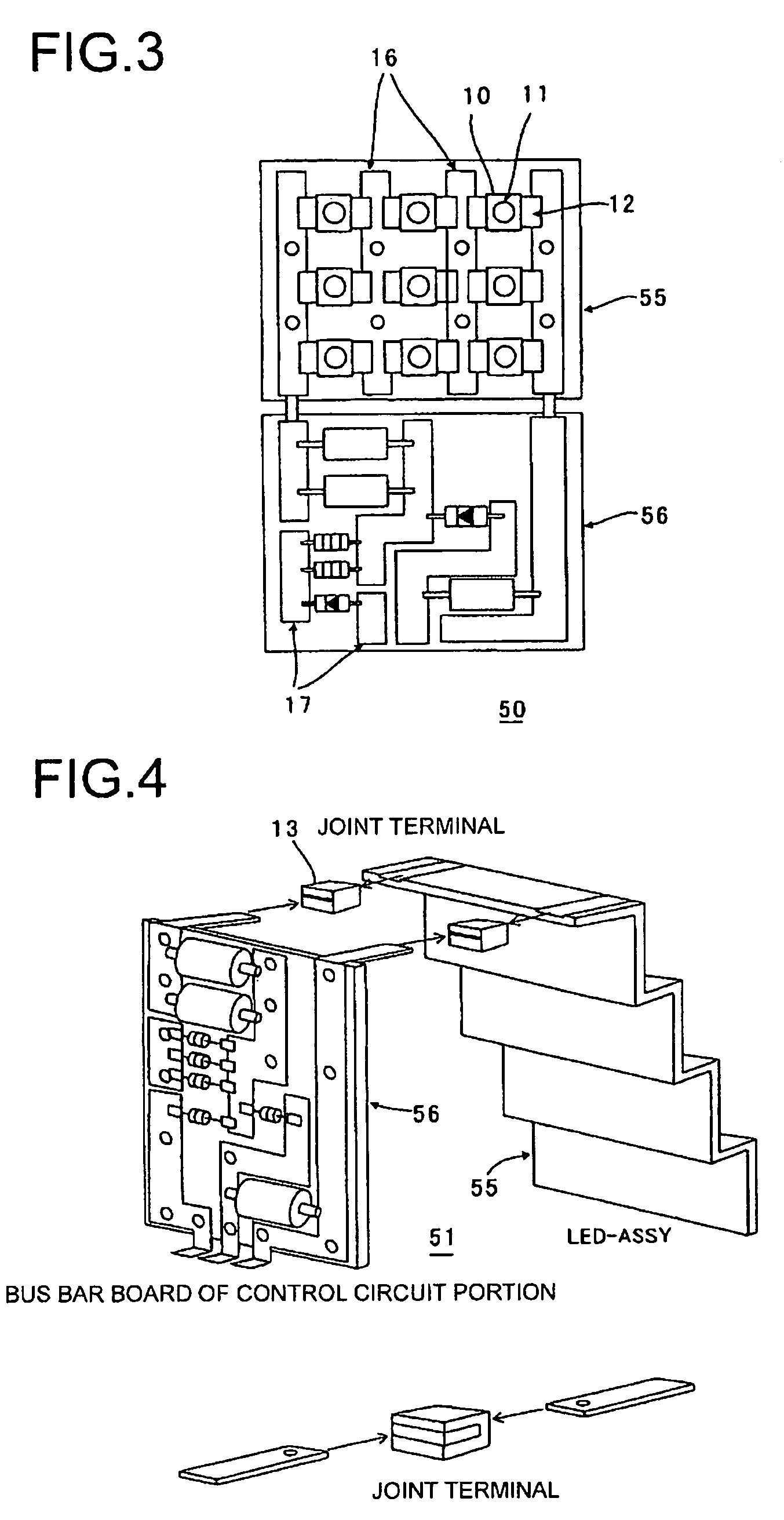
[0031]A tail and stop lamp 100 is mainly structured from a lamp body 1, a curved front cover 2, a lamp chamber 3 that is defined by the lamp body 1 and the front cover 2, a curved reflector 4 that is disposed inside the lamp chamber 3, and a bus bar unit 5 that is provided on the back side of the reflector 4. The bus bar unit 5 is a unit provided with an LED light source assembly portion 55 that is mounted with an LED 10, which acts as a light source of the tail and stop lamp 100, and a control circuit portion 56 that controls the light emission of the LED. In the example shown in the drawing, the bus bar unit 5 is fixed to the reflector 4 on a vehi...


PUM


Abstract

A vehicular lamp includes a lamp body; a plurality of LED light sources disposed inside a lamp chamber formed by a front cover positioned in front of the lamp body; and a lighting circuit portion positioned behind the LED light sources. The LED light source is electrically connected to a conductive bus bar, and forms a light-emitting surface at a position opposite the front cover. The lighting circuit portion is formed on the back side of the light-emitting surface of the LED light source with respect to the front cover, and a circuit element thereof is electrically connected to the conductive bus bar. The conductive bus bar to which the LED light source is connected and the conductive bus bar to which the circuit element is connected are conductively connected.

Description

BACKGROUND OF INVENTION[0001]1. Field of the Invention[0002]The present invention relates to a vehicular lamp using an LED as a light source.[0003]2. Background Art[0004]In recent years, a variety of LEDs with excellent light emission efficiency and power consumption characteristics are being used as a light source in a vehicular lamp (see Patent Document 1 for an example). Such a vehicular lamp is provided with an LED light source assembly portion mounted with an LED and a unit that combines the LED light source assembly portion with a control circuit portion. As shown in FIG. 12, a conventional control circuit portion uses a printed circuit board 8, which is connected to the back side of the LED light source assembly portion by a jump cord 15.[0005][Patent Document 1] U.S. Pat. No. 6,715,909SUMMARY OF INVENTION[0006]In order to make a smaller overall unit, it is preferable that the control circuit portion and an LED light source assembly portion 9 are arranged adjacent to one anot...

Claims


Application Information

Patent Timeline
Patent Type & Authority Patents(United States)
IPC IPC(8): B60Q1/02F21W107/10
CPCB60Q1/0094F21S48/212F21S48/215H05K1/0284H05K1/148B60Q1/2696H05K2203/302H05K1/14H05K1/189H05K3/202H05K3/328H05K2201/10106H05K2201/10272H05K2201/10287H05K2201/10651F21S43/14F21S43/195
Inventor TSUKAMOTO, HIRONORIITO, NORIAKI
Owner KOITO MFG CO LTD
Why Eureka
Try Eureka