Video monitoring and conferencing system

a video monitoring and conferencing system technology, applied in the field of video monitoring, can solve the problems of inability to store large quantities or sequences of images, signal is susceptible to disturbance, limited storage capacity, etc., and achieve the effect of prolonging recording tim

Inactive Publication Date: 2012-06-12
HAWK TECH SYST
View PDF176 Cites 27 Cited by
  • Summary
  • Abstract
  • Description
  • Claims
  • Application Information

AI Technical Summary

Benefits of technology

[0015]It is a further object of the invention to provide extended recording time for event-logging or security applications by means of either tape-based, or disk-based, or both tape-based and disk-based data recording means.

Problems solved by technology

Storage capacity is limited, however, because no image data compression is provided, and it is not practical to store large quantities or sequences of images.
However, Gormley clearly indicates that the system relies on fixed image-size compression of the digitized incoming video signal, and does not perform any kind of bandwidth compression.
As such, these signals are susceptible to disturbances such as RF interference, ground-loop noise, and high-frequency signal loss due to long runs of coaxial cables.
When such a system is equipped with a time-lapse video recorder, the recording medium is expensive, has low resolution, and is limited in recording capacity.
This system, however, has no provisions for image storage, or any application of image data compression means coupled with display means or image storage means.

Method used


Image

  • Video monitoring and conferencing system
  • Video monitoring and conferencing system
  • Video monitoring and conferencing system

Examples


Embodiment Construction

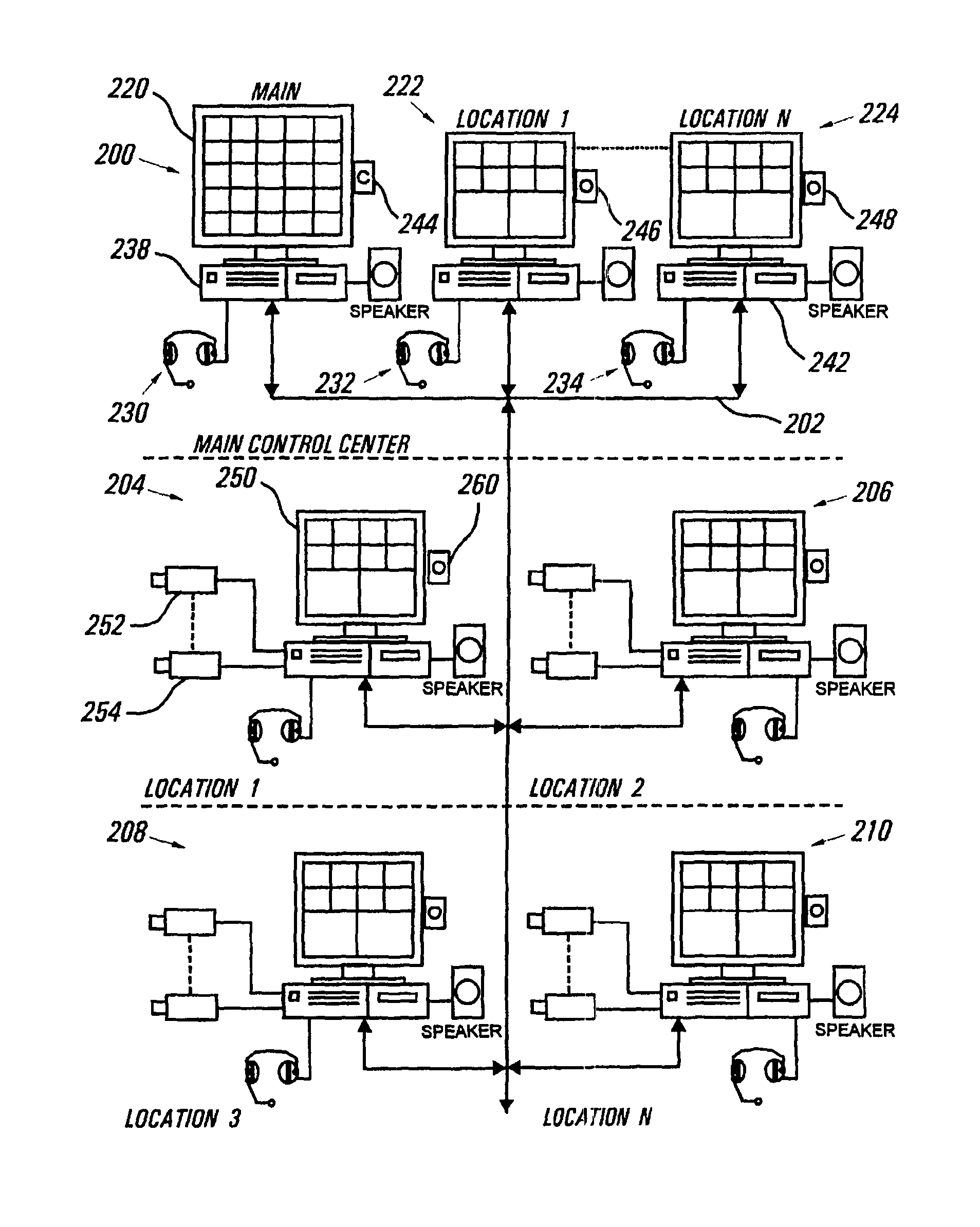
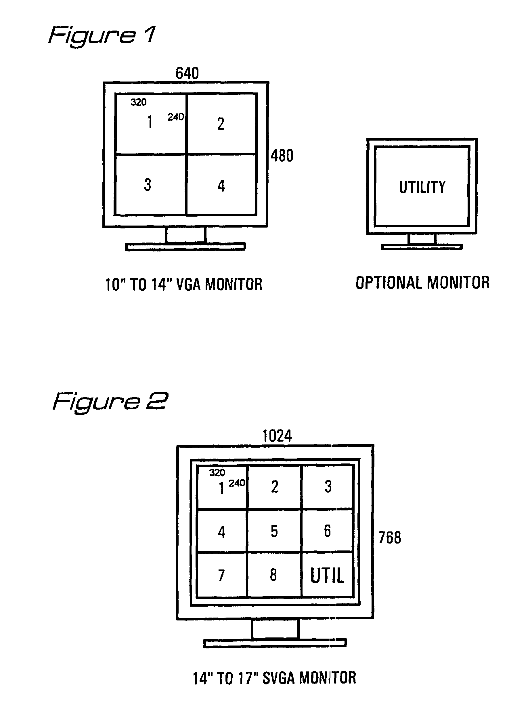
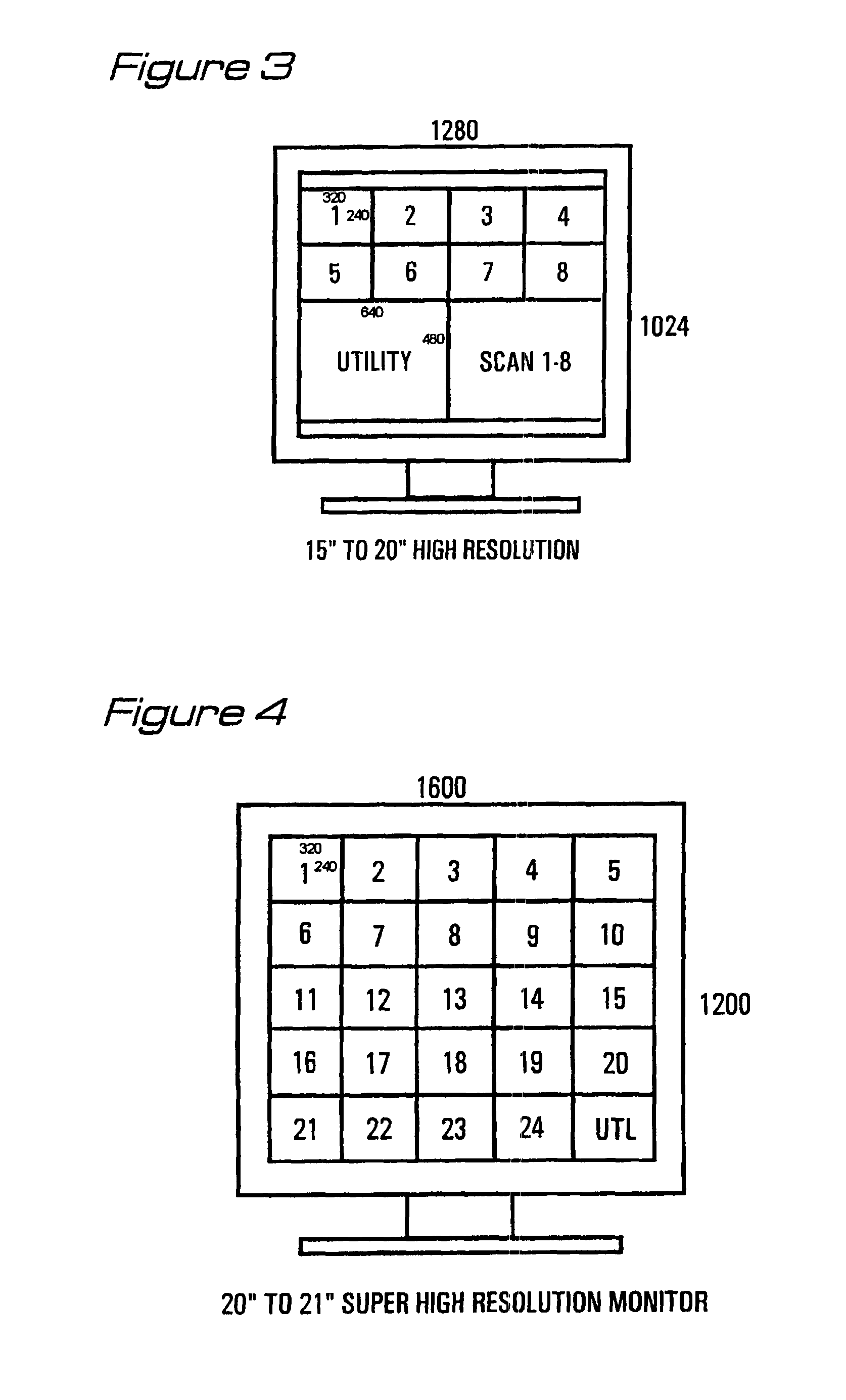
[0028]The present invention implements an automated video monitoring system by way of a PC-based platform employing display windowing software, with camera sources being interfaced to an input circuit board which includes provisions for image data compression. The basic video window size of 320×240 pixels from each camera source can be displayed on a variety of video monitors, in a number of formats, depending on system complexity. The preferred recording medium is a 4-mm helical-scan data cartridge, commonly referred to as a digital audio tape (DAT). Each tape cartridge is capable of storing 10 GB (gigabytes) of data. All recording times in the explanation below are based a data-compression ratio of 100:1, utilizing a 4:2:2 Y / U / V sampling method for color images. Other higher capacity media, such as 8-mm tapes capable of 20 GB of data storage, may be employed when longer times are desired.

[0029]FIG. 15 shows a variety of possible operating modes, depending on the particular impleme...


PUM


Abstract

A PC-based system for monitoring and storing representative images from video cameras may be utilized for security or other monitoring applications. Camera inputs from digital or analog sources are individually and independently digitized and displayed at a first set of image sizes, sampling rates, and frame rates, and may be stored in digital form on various recording media at a second set of image sizes, sampling rates, and frame rates, and these two sets of sizes and rates may or may not be identical. Provisions are included for adding detection or alarm systems which will automatically alter image size, sampling rate and / or frame rate of an individual input source, or activate other physical responses. In addition to security system monitoring, further applications of the invention are disclosed for process monitoring in manufacturing environments and also for applications in videoconferencing.

Description

REFERENCE TO RELATED APPLICATIONS[0001]This application is a continuation-in-part of U.S. Ser. No. 08 / 050,861, filed Apr. 21, 1993 now U.S. Pat. No. 5,450,140 and Ser. No. 08 / 298,104, filed Aug. 30, 1994 now U.S. Pat. No. 5,537,157.FIELD OF THE INVENTION[0002]This invention relates generally to video monitoring, and, more particularly, to such systems employing means for digitizing camera images for display at a first image size, sampling rate, and frame rate, and for digital storage at a second image size, sampling rate, and frame rate.BACKGROUND OF THE INVENTION[0003]Existing systems for monitoring video signals from multiple sources either have relied upon switching means to sequence through each of the sources in a predetermined pattern, or else implement some form of “split screen” display, in which a conventional video monitor displays, for example, the output of four cameras, each occupying a portion of the display screen. Often, the video output is also supplied to signal st...

Claims


Application Information

Patent Timeline
Patent Type & Authority Patents(United States)
IPC IPC(8): H04N7/18
CPCG06F3/14G06T9/007G11B27/031G11B27/032G11B27/34H04N5/222H04N5/23203H04N5/247H04N5/765H04N5/77H04N7/102H04N7/181H04N9/8042H04N21/4143H04N21/4223H04N21/4316H04N21/4334H04N21/440263H04N21/440281H04N21/4622H04N21/4788G06F3/1454G09G2340/02G09G2340/0407G09G2340/0442G11B27/002G11B27/024G11B27/034G11B2220/20G11B2220/2516G11B2220/2525G11B2220/41G11B2220/455G11B2220/61G11B2220/90G11B2220/913H04N5/4401H04N5/772H04N5/781H04N5/85H04N5/915H04N9/641H04N9/642H04N9/8063H04N9/896G06F3/1423H04N7/104G09G5/14G09G2340/0435H04N21/47H04N23/66H04N23/661H04N23/63H04N23/90
Inventor WASHINO, KINYASCHWAB, BARRY H.
Owner HAWK TECH SYST
Why Eureka
Try Eureka