

Bias assembly for ratchet tools
a ratchet wrench and assembly technology, applied in the field of ratchet pawl assemblies, can solve the problems of high torque needed to tighten or loosen the bolt, limited access to the bolt, awkward and difficult to use a traditional (non-ratcheting) tool, etc., to minimize the amount of counter-rotation, minimize the amount of wasted motion, and minimize the effect of playing in the ratchet wrench
- Summary
- Abstract
- Description
- Claims
- Application Information
AI Technical Summary
Benefits of technology
Problems solved by technology
Method used
Image

Examples
Embodiment Construction
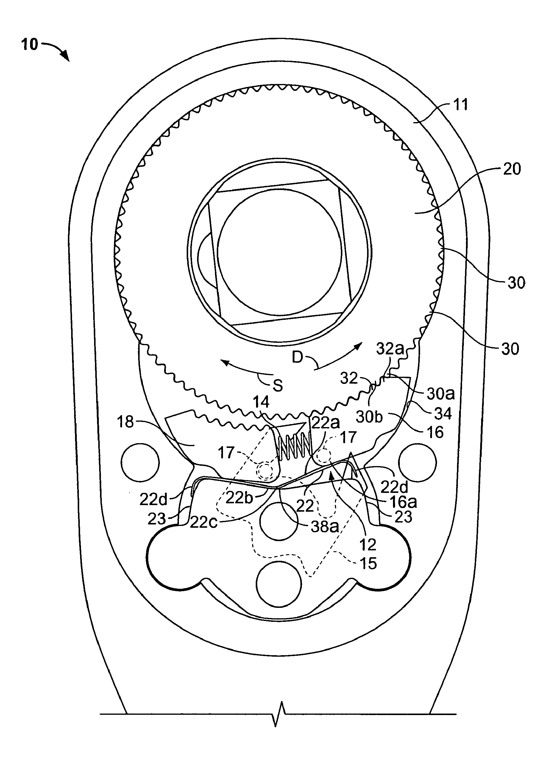
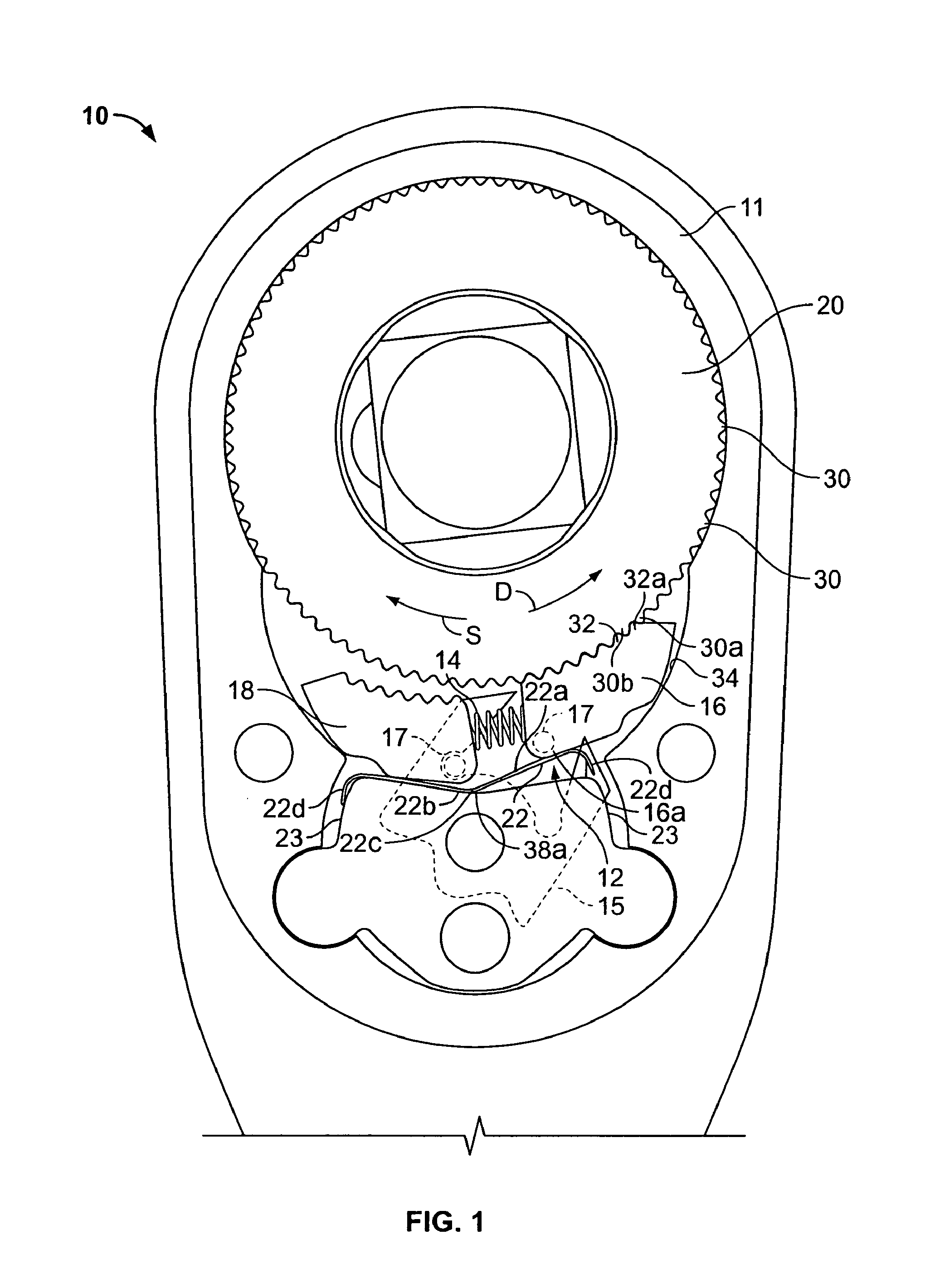
[0025]Referring initially to FIG. 1, a ratchet head 10 of a ratchet wrench is shown having a body 11 and a bias assembly 12 for reducing waste rotation when the wrench is rotated and counter-rotated. In the present form, the bias assembly 12 includes a first spring 14, referred to herein as the selection spring 14, for biasing first and second pawls 16, 18 apart. The first and second pawls 16, 18 are selectively engagable with a ratchet gear 20 to select a drive direction and a slip or ratchet direction respectively corresponding to rotation and counter-rotation of the ratchet head 10. The selection spring 14 allows a reversing lever or drive direction selector or actuator 15 to act upon posts 17 of the pawls 16, 18 so that the selector 15 may shift one of the pawls 16, 18 into or out of engagement with the gear 20, and the selector spring 14 serves to shift the other of the pawls 18, 16 in the opposite manner as the one pawl 16, 18. Preferably, the selector 15 is operated to pull o...
PUM
 Abstract
Description
Claims
Application Information