
Axial plunger pump

A technology of axial piston pump and plunger, which is applied in the direction of pumps, multi-cylinder pumps, liquid displacement machinery, etc., can solve the limitation of the PV allowable value of the friction pair of the distribution plate, the difficulty of realizing large displacement and high pressure pumps, Problems such as mechanical vibration cannot be eliminated, so as to achieve the effect of improving service life, reducing radial size and eliminating interference

Inactive Publication Date: 2007-09-05
LANZHOU UNIVERSITY OF TECHNOLOGY
View PDF7 Cites 0 Cited by
  • Summary
  • Abstract
  • Description
  • Claims
  • Application Information

AI Technical Summary

Problems solved by technology

[0003] 1) Due to the direct connection between the drive shaft and the cylinder (rotor), the external mechanical vibration cannot be eliminated;
[0004] 2) For axial piston pumps with disk distribution, the pv allowable value of the friction pair of the distribution disk is limited to a certain extent, and it is difficult to achieve large displacement and high pressure pumps
[0006] 1) The radial dimension is large, so it is not suitable to be used in some occasions that have strict requirements on the radial dimension;
[0007] 2) Due to the special structure of the radial piston pump, its failure rate is high

Method used


Image

  • Axial plunger pump
  • Axial plunger pump
  • Axial plunger pump

Examples


Embodiment Construction

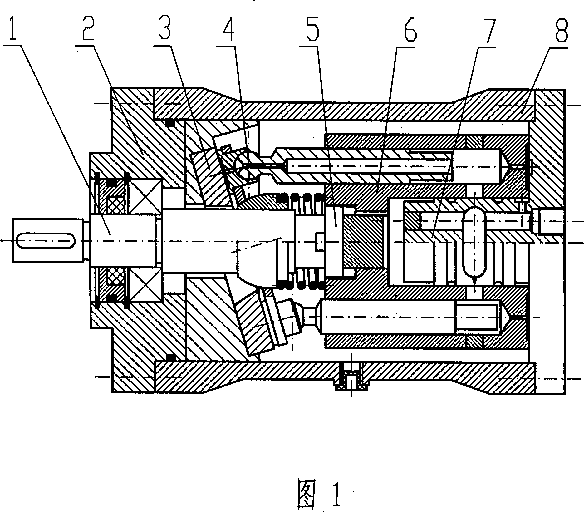
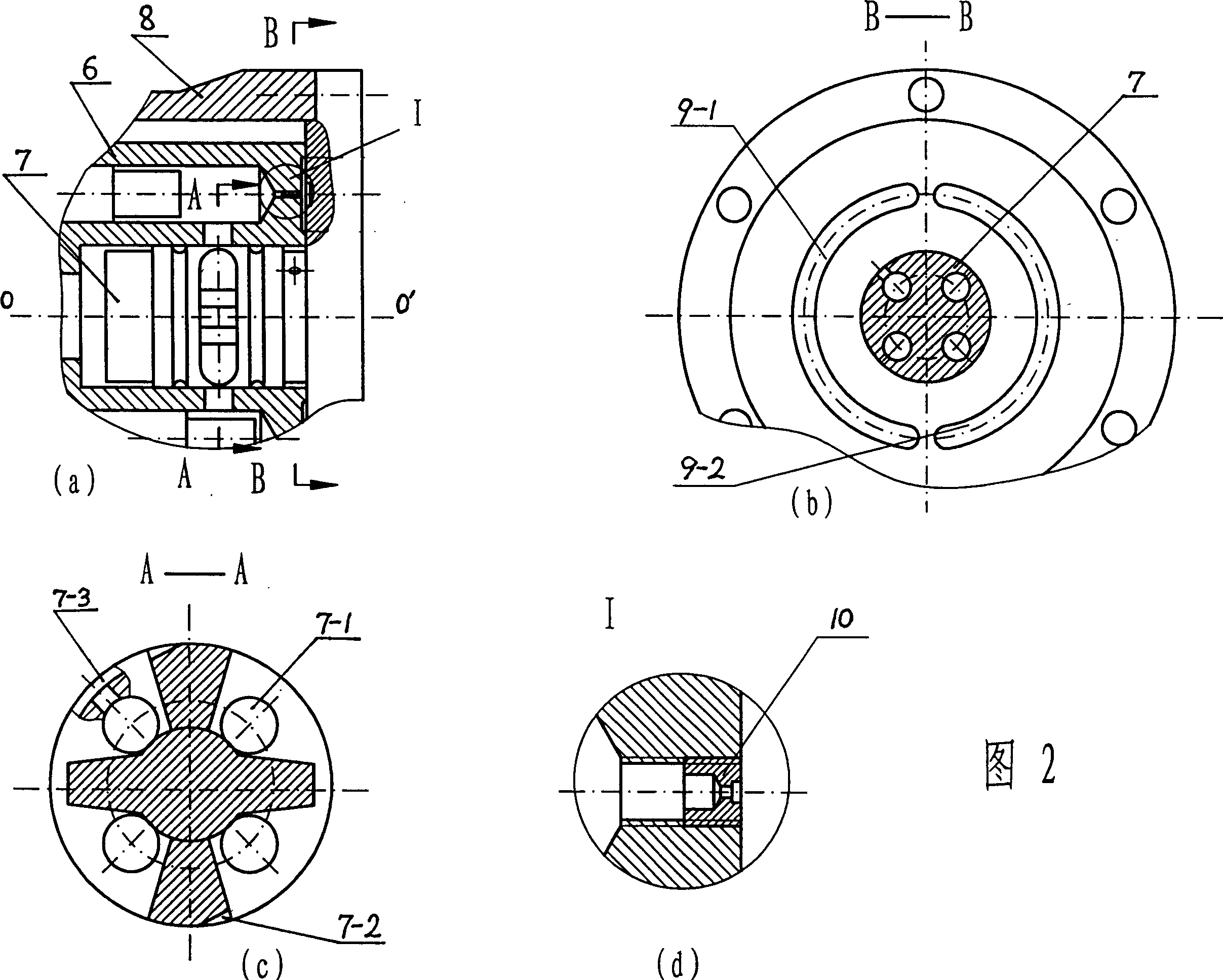
[0018] As shown in Figure 1, the present invention includes a main transmission shaft 1, a pump body 8, an end cover 2, a flow distribution shaft 7, a swash plate 3, and a cylinder body 6, the cylinder body 6 is installed in the pump body 8, and the sliding shoe plunger group 4 Placed in the cylinder body 6 and extended to support the swash plate 3, the sliding shoe plunger group 4 and the Oldham slider group 5 docked with the main transmission shaft 1 together form a rotating part, and the distribution shaft 7 is placed in the cylinder body 6. The main transmission shaft 1 drives the cross slider group 5 to rotate under the drive of the motor or the like.

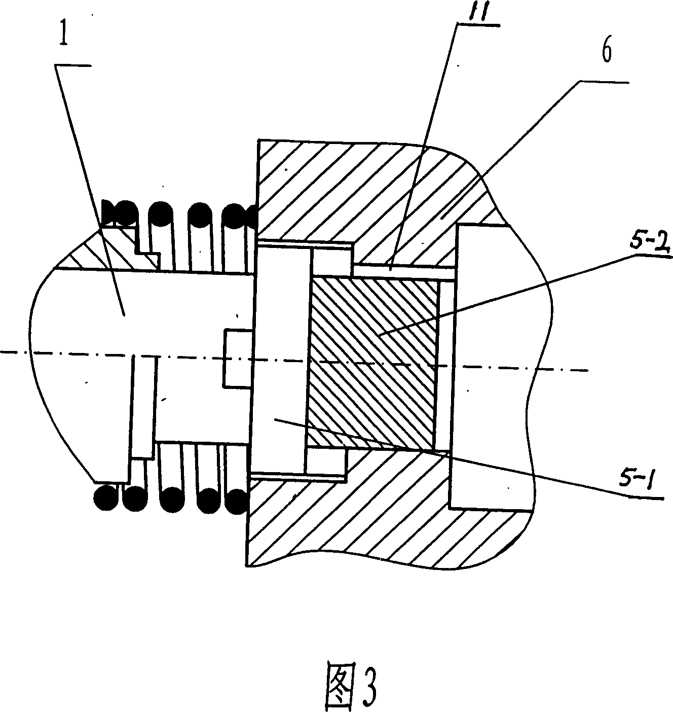
[0019] As shown in Figure 1 and Figure 3, the main slider 5-2 at the right end of the cross slider group 5 is connected to the cylinder body 6, the cylinder body 6 rotates and drives the sliding shoe plunger group 4 to rotate, and the sliding shoe plunger group 4 is Press it on the swash plate 3, so that each plunger rotat...


PUM


Abstract

This invention is a kind of axis direction pillar pump, its purpose is to comprehensive the main advantage of the axis direction pillar pump and the pump of pillar of radial, overcome each comfortable structure of main corrupt practice, a set of crosshead of left carry to spread with lord to move the stalk coupling, a set of crosshead slippery piece of right side carry to connect with the body, through the center slippery piece coupling with the main transmission, the flow axis drive be install in the pump body fixedly, open the oil enter and exit on the flow stalk, high low pressure flow slot and equilibrium slot of pressure, make the body of revolve urn suspend on the flow stalk. This invention makes the path size of the flow structure decreased consumedly, lowers the circumference speed of the pump of fill pillar significant, removing the exterior machine vibration to revolve the interference of the part to the pump, can carry out the balance of the dint to stalk body, kept the suspend state when body of urn moving, reduced abrasion, raised the service life.

Description

technical field [0001] The present invention relates to liquid displacement machines, especially hydraulic transmission devices. Background technique [0002] The axial plunger pump and the radial plunger pump adopted in the prior art have many advantages, but both also have disadvantages. The disadvantages of axial piston pumps are: [0003] 1) Due to the direct connection between the drive shaft and the cylinder (rotor), the external mechanical vibration cannot be eliminated; [0004] 2) For axial piston pumps with disk distribution, the allowable pv value of the friction pair of the distribution disk is limited to a certain extent, and it is difficult to achieve large displacement and high pressure pumps. [0005] The disadvantages of radial piston pumps are: [0006] 1) The radial dimension is large, so it is not suitable to be used in some occasions that have strict requirements on the radial dimension; [0007] 2) Due to the special structure of the radial piston p...

Claims


Application Information

Patent Timeline
Patent Type & Authority Patents(China)
IPC IPC(8): F04B1/12F16H47/00
Inventor 乔丰立唐兵杨国来卢堃
Owner LANZHOU UNIVERSITY OF TECHNOLOGY
Learn More