Piston transmission mechanism and two-dimensional compressor

A technology of piston transmission and compressor, applied in the field of compressors, can solve the problems of large leakage, high rotational speed of screw compressors, difficult to reach, etc., and achieve the effects of reducing frictional resistance, increasing working speed and reducing production costs.

Active Publication Date: 2019-01-15
JIAXING UNIV +1
View PDF7 Cites 5 Cited by
  • Summary
  • Abstract
  • Description
  • Claims
  • Application Information

AI Technical Summary

Problems solved by technology

The piston compressor has a lot of vibration and noise, and it is difficult to achieve high speed. The air valve is a key part of the piston compressor, and the air valve is a vulnerable part
The rolling rotor compressor has fewer parts than the piston compressor, and its volume and weight are smaller than that of the piston compressor, but there is a relatively high speed of motion between the rotor and the cylinder, resulting in greater friction and wear, and greater rotational inertia force, causing vibration and noise
The scroll compressor has stable output gas, low noise and vibration, but the design of the scroll profile is difficult, and the processing accuracy is high, there is a large friction and wear, and the sealing requirements are high. It is difficult to achieve a large compression ratio on the medium and high pressure compressors.
Screw compressors can be divided into two categories: ordinary screw compressors and oil-free screw compressors. The core components are a pair of intermeshing rotors. There are no suction and discharge valves, few wearing parts, good balance, and small vibration. , high reliability, but the speed of the screw compressor is relatively high, resulting in high noise, complicated design and processing, large leakage, and low output gas pressure
Centrifugal compressors have few moving parts, high speed, large gas volume, and stable operation, but there is a narrow stable working area, which is not suitable for occasions where the gas volume is too small and the pressure ratio is too high

Method used


Image

  • Piston transmission mechanism and two-dimensional compressor
  • Piston transmission mechanism and two-dimensional compressor
  • Piston transmission mechanism and two-dimensional compressor

Examples


Embodiment 1

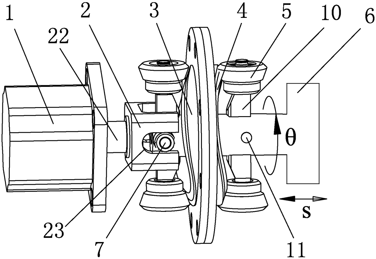
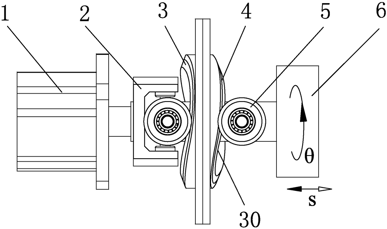
[0051] Such as Figure 1 to Figure 4 As shown, a piston transmission mechanism includes a motor 1 and a piston shaft 6. The motor 1 has an output shaft 22, and the output shaft 22 is fixedly provided with a shaft coupling 2 that rotates synchronously with it. 22 is provided with a side groove 23 in the axial direction, and a pin shaft 7 is fixedly arranged on the outside of the piston shaft 6, and a needle bearing 12 is installed inside the pin shaft 7, and the needle roller bearing 12 is limited to the side groove 23 and forms a sliding motion with the side groove 23. Cooperate;

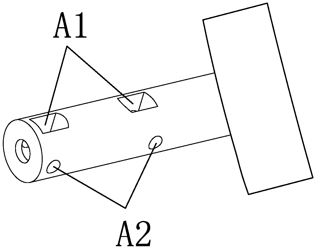
[0052] The piston shaft 6 is sequentially provided with two rotating shaft holes A1 arranged at intervals, and each rotating shaft hole A1 is respectively inserted with a rotating shaft 10 limited in its own rotating shaft hole A1, and the position of the piston shaft 6 corresponding to each rotating shaft hole A1 is provided with a pin hole A2, Each pin hole A2 is inserted with a fastening pin 11 ...

Embodiment 2

[0055] A two-dimensional piston compressor composed of a piston transmission mechanism described in Embodiment 1, the two-dimensional piston compressor includes a single-stage two-dimensional piston compressor, a two-stage two-dimensional piston compressor and a three-stage two-dimensional piston compressor. Piston compressor.

[0056] Such as Figure 5 to Figure 9 As shown, Embodiment 2 is a single-stage two-dimensional piston compressor, including a single-stage cylinder 15 fixedly connected to a piston transmission mechanism, and the piston shaft 6 is a single-stage piston shaft 14 .

[0057] Such as Figure 5 with Image 6 As shown, the shaft of the single-stage piston shaft 14 is provided with a rotating shaft hole A1 and a pin hole A2, and the piston of the single-stage piston shaft 14 is provided with radially symmetrically distributed single-stage piston grooves A3; Figure 7 As shown, the single-stage cylinder 15 is provided with radially symmetrically distributed ...

Embodiment 3

[0061] Such as Figure 10 to Figure 15 As shown, Embodiment 3 is a two-stage two-dimensional piston compressor, including a two-stage cylinder 17 , which is fixedly connected with the piston transmission mechanism, and the piston shaft 6 is the two-stage piston shaft 16 .

[0062] Such as Figure 10 with Figure 11 As shown, the shaft of the secondary piston shaft 16 is provided with a rotating shaft hole A1 and a pin hole A2, and the piston of the secondary piston shaft 16 is provided with a radially symmetrical secondary piston groove A4; as Figure 12 with Figure 13 As shown, the secondary cylinder block 17 is provided with a radially symmetrically distributed secondary compression outlet O3 and a secondary compressed air inlet O4, and the inner wall of the secondary cylinder block 17 is provided with a radially symmetrically distributed secondary cylinder The first-stage exhaust groove B1 of the body and the second-stage exhaust groove B2 of the secondary cylinder bloc...


PUM


Abstract

The invention discloses a piston transmission mechanism which comprises a motor and a piston shaft. The motor has an output shaft which is fixedly provided with a coupling, the coupling is provided with a side groove, and a piston shaft is provided with a needle bearing which is limited in the side groove with a sliding fit. The piston shaft is orderly provided with two rotating shaft holes, a rotating shaft is inserted into each of the rotating shaft holes, at least one end of the each of the rotating shafts is fixedly provided with a roller, a raceway is fixedly arranged between the rotatingshafts, and a left cam raceway and a right cam raceway are symmetrically distributed at two sides of raceway and are provided with cam curved surfaces. When the output shaft rotates, the coupling drives the piston shaft to rotate, and the rollers on the rotating shafts roll along the cam curved surfaces on the corresponding left cam raceway and right cam raceway to allow the piston shaft to reciprocate linearly along the central axis of the piston shaft. The piston transmission mechanism has the advantages of light weight, high pressure, high efficiency, oil-free compression and low noise andvibration.

Description

technical field [0001] The invention relates to the technical field of compressors, in particular to a piston transmission mechanism and a two-dimensional compressor. Background technique [0002] The function of the compressor is to convert the mechanical energy into the pressure energy of the gas to increase the output pressure of the gas. It is a general-purpose machine with a wide range of uses, such as air conditioners and refrigerators, pneumatic transmission, gas transportation, chemical fuels, etc. Commonly used compressors mainly include piston compressors, rolling rotor, vane, scroll and screw compressors, and centrifugal compressors. Piston compressors have large vibration and noise, and it is difficult to achieve high speed. The air valve is a key part of the piston compressor, and the air valve is a vulnerable part. The rolling rotor compressor has fewer parts than the piston compressor, and its volume and weight are smaller than that of the piston compressor, ...

Claims


Application Information

Patent Timeline
Patent Type & Authority Applications(China)
IPC IPC(8): F04B35/04F04B27/08F04B39/12F04B39/00
CPCF04B27/0895F04B35/04F04B39/00F04B39/0005F04B39/0022F04B39/0027F04B39/122
Inventor 赵伟阮健赵建涛宋占凯张海军钱承李伟荣
Owner JIAXING UNIV
Why Eureka
Try Eureka