Fault collection and detection apparatus and method

A fault acquisition and detection device technology, applied in the direction of measuring devices, data acquisition and recording, instruments, etc., can solve the problems of increasing production costs, large volume of industrial computer, high price of industrial computer, etc., to prevent mutual interference and complicate power supply circuit degree of reduction, the effect of reducing power consumption

Inactive Publication Date: 2007-09-12
ZHEJIANG UNIV
View PDF3 Cites 3 Cited by
  • Summary
  • Abstract
  • Description
  • Claims
  • Application Information

AI Technical Summary

Problems solved by technology

[0003] Hand-held data collectors popular at home and abroad in the 1990s were widely used in industrial sites because of their small size and easy portability. However, because most of their core chips are 8-bit single-chip microcomputers, the processing capacity is limited, and they can only collect single-channel data collectors. The instantaneous amplitude, peak-to-peak value and other discrete fast variables of the vibration signal, as well as the slow variables such as temperature and flow, cannot realize the high sampling rate acquisition of multi-channel real-time fast-changing data and the synchronous dynamic time-frequency domain display and comparative analysis of historical data. Adapt to the needs of key equipment system monitoring and fault pre-judgment
Replacing the hand-held data acquisition instrument with the system of industrial computer plus data acquisition card can meet the requirements of important industrial occasions for the speed and performance of equipment operation data sampling and processing, but due to the relatively large size of the industrial computer, it is difficult to Use one fault diagnosis instrument to comprehensively monitor multiple related equipment; in addition, due to the relatively high price of industrial computers, if each device is equipped with a fault diagnosis instrument, the production cost will be greatly increased

Method used


Image

  • Fault collection and detection apparatus and method
  • Fault collection and detection apparatus and method
  • Fault collection and detection apparatus and method

Examples


Embodiment Construction

[0027] The present invention will be further described below in conjunction with accompanying drawing and embodiment:

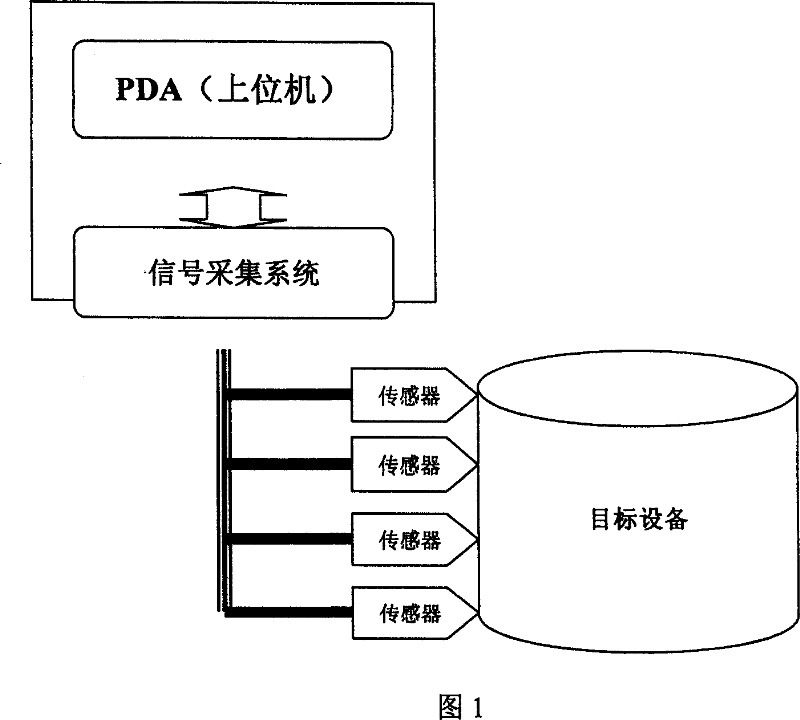
[0028] Fig. 1 has provided the connection diagram of the present invention in the field. The on-site vibration sensor can be fixed in multiple orientations of the target equipment, such as the X radial, Y radial, axial, etc. Equipment operation data such as vibration amplitude. The hardware circuit of the lower computer includes MCU part, power supply part, analog part, external expansion SRAM and serial port part.

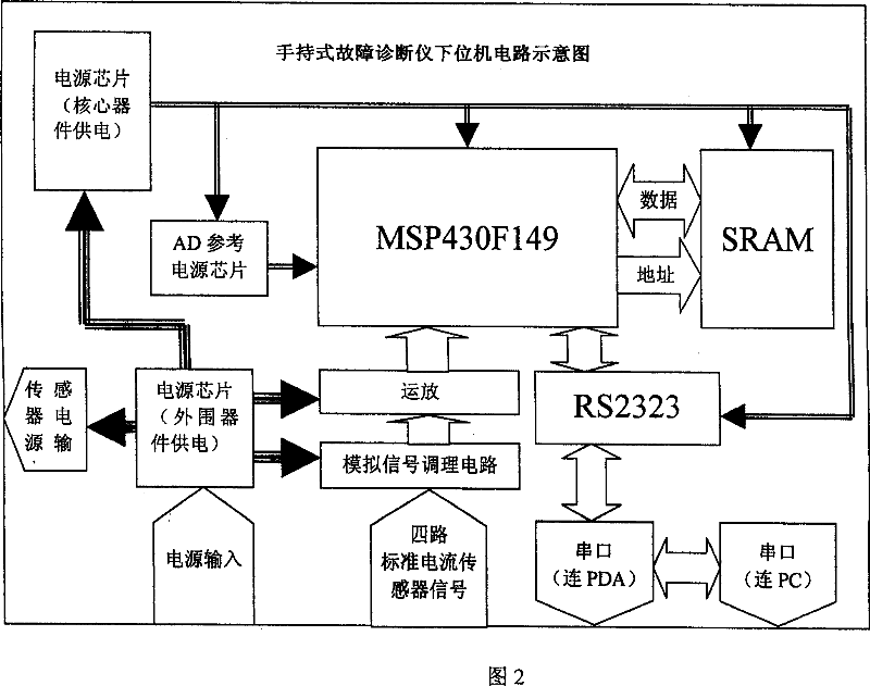
[0029] Figure 2 is the overall frame diagram of the hardware of the lower computer. The multi-channel sensor analog signal connected to the target device in the industrial field passes through the signal conditioning circuit to obtain the spectrum range signal that needs to be collected, and then passes through the integrated operational amplifier to amplify the signal to the input voltage range of the AD inside the MCU. The integrated AD of t...


PUM


Abstract

This invention relates to a fault collection detecting apparatus and its method and the system comprises upper computer and down computer. The down computer adopts data collection board and is used to data collection of multiple-path spot and buffer and pre-process, while the upper computer adopts PDA and receives the sent data by the down computer through the serial port. The down computer realizes the whole spot monitor tasks, such as analog signal collection, AD conversion and simple data process part and controls the hardware scale and power consumption of the system. The upper computer realizes the further data process, spot real time analysis display element, history data re-display.

Description

technical field [0001] The invention relates to the field of data collection and detection, and mainly relates to a fault collection and detection device and method for monitoring the operating state of large and medium-sized rotating electromechanical equipment and pre-judging faults. Background technique [0002] With the development of modern industry, large and medium-sized rotating electromechanical equipment (such as water pumps, blowers, steam turbines, etc.) are increasingly widely used in industrial sites. Since these devices are often the core equipment produced by the enterprise, once a failure occurs, the equipment itself will be damaged, and the production of the entire enterprise will be affected, and even personal casualties may occur. are getting more and more attention. [0003] Hand-held data collectors popular at home and abroad in the 1990s were widely used in industrial sites because of their small size and easy portability. However, because most of the...

Claims


Application Information

Patent Timeline
Patent Type & Authority Patents(China)
IPC IPC(8): G06F17/40G06F13/38G01D21/02
CPCY02B60/1228Y02B60/1235Y02D10/00
Inventor 吴朝晖陈尚俭李培玉王磊杨国青郑能干吴伟清吕攀
Owner ZHEJIANG UNIV
Why Eureka
Try Eureka