Pressurization type generator of marsh gas

A generator and biogas technology, applied in the direction of gas production bioreactors, waste fuels, etc., can solve the problems of small gas production, slow gas production speed, low cost, etc., and achieve the effect of stable gas source pressure and convenient refueling

Inactive Publication Date: 2007-10-10
王海金
View PDF3 Cites 0 Cited by
  • Summary
  • Abstract
  • Description
  • Claims
  • Application Information

AI Technical Summary

Problems solved by technology

[0002] Biogas is widely used in remote mountainous areas and rural areas, but currently known biogas generators have slow gas production speed and low pressure, and it is difficult to pressurize the produced gas. Most of them are used according to the pressure of biogas output, so the pressure Poor stability, small gas production per unit time, affecting the normal use of biogas appliances
In addition, general biogas generators are built underground, occupying a small area and low cost. Although it is convenient to feed materials, it is very troublesome to discharge materials. Biogas generators cannot be mass-produced and popularized, which also affects the stability of manufacturing quality. sex

Method used


Image

  • Pressurization type generator of marsh gas
  • Pressurization type generator of marsh gas
  • Pressurization type generator of marsh gas

Examples


Embodiment 1

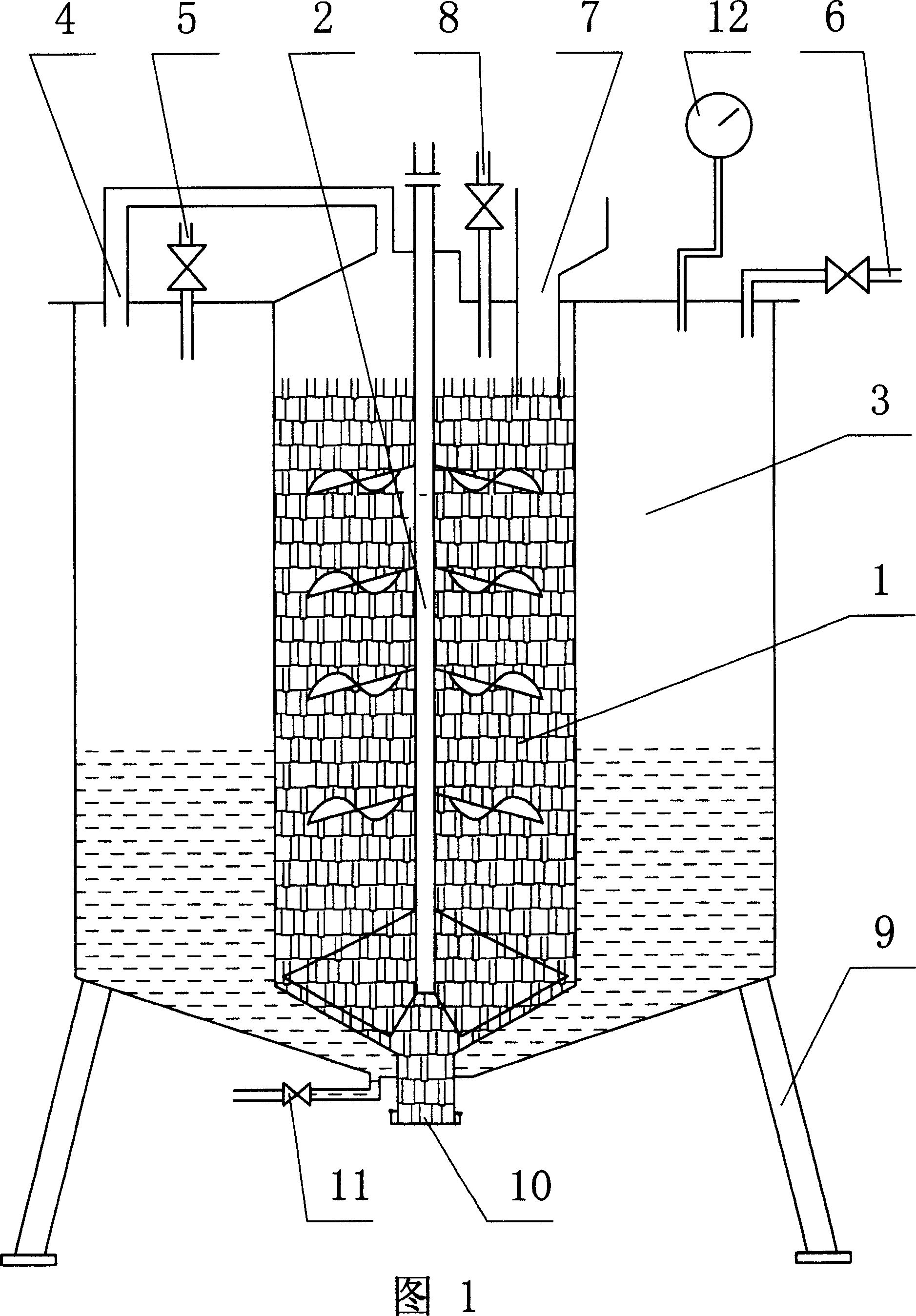
[0018] As shown in Figure 1, there is a biogas generating chamber 1 in the middle, a stirrer 2 is installed in the generating chamber 1, and a pressurized chamber 3 is formed on the periphery of the generating chamber 1, and the upper ends of the generating chamber 1 and the pressurized chamber 3 pass through the air duct 4 are connected, the water inlet pipe 5 is externally connected to the pressurization chamber 3, and the gas outlet pipe 6 is connected to the upper end of the pressurization chamber 3, which can be connected with the biogas appliance. 8. The bottom of the pressurization chamber 3 is shaped on a support foot 9, which is movable as a whole. An openable discharge port 10 is formed at the bottom of the generation chamber 1 . A drain valve 11 is installed at the bottom of the boost chamber 3 . The top of the pressurization chamber 3 is also provided with an air pressure indicating gauge 12 .

[0019] The working principle is: add raw materials such as straw, h...

Embodiment 2

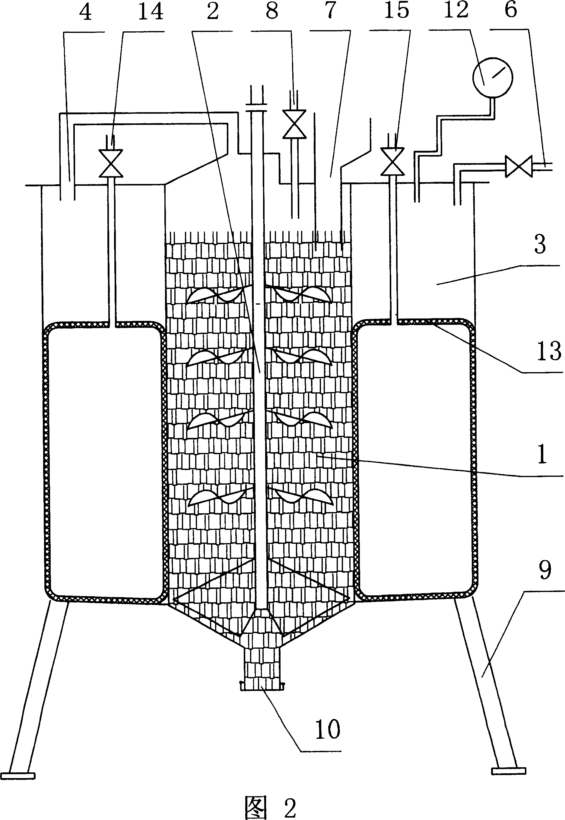
[0021] Fig. 2 is a structural principle diagram of a biogas booster generator with a booster chamber equipped with a booster air bag. Compared with embodiment 1, its pressurization mode is that a pressurized air bag 13 is provided in the pressurized chamber 3 , and the intake pipe 14 and the deflation valve 15 communicate with the pressurized air bag 13 . When the air pressure in the pressurized chamber 3 is too low, close the release valve 15 and communicate with the pressurized air bag 13 . When the air pressure in the pressurization chamber 3 was too low, the air release valve 15 was closed, and the pressurized air bag 13 in the pressurized chamber 3 was inflated by the intake pipe 14, so that the volume of the pressurized air bag 13 was increased, and the air pressure in the pressurized chamber 3 was increased. The biogas pressure increased rapidly. When the biogas is not in use, the air release valve 15 can be opened, and the air in the pressurized air bag 13 can be rele...

Embodiment 3

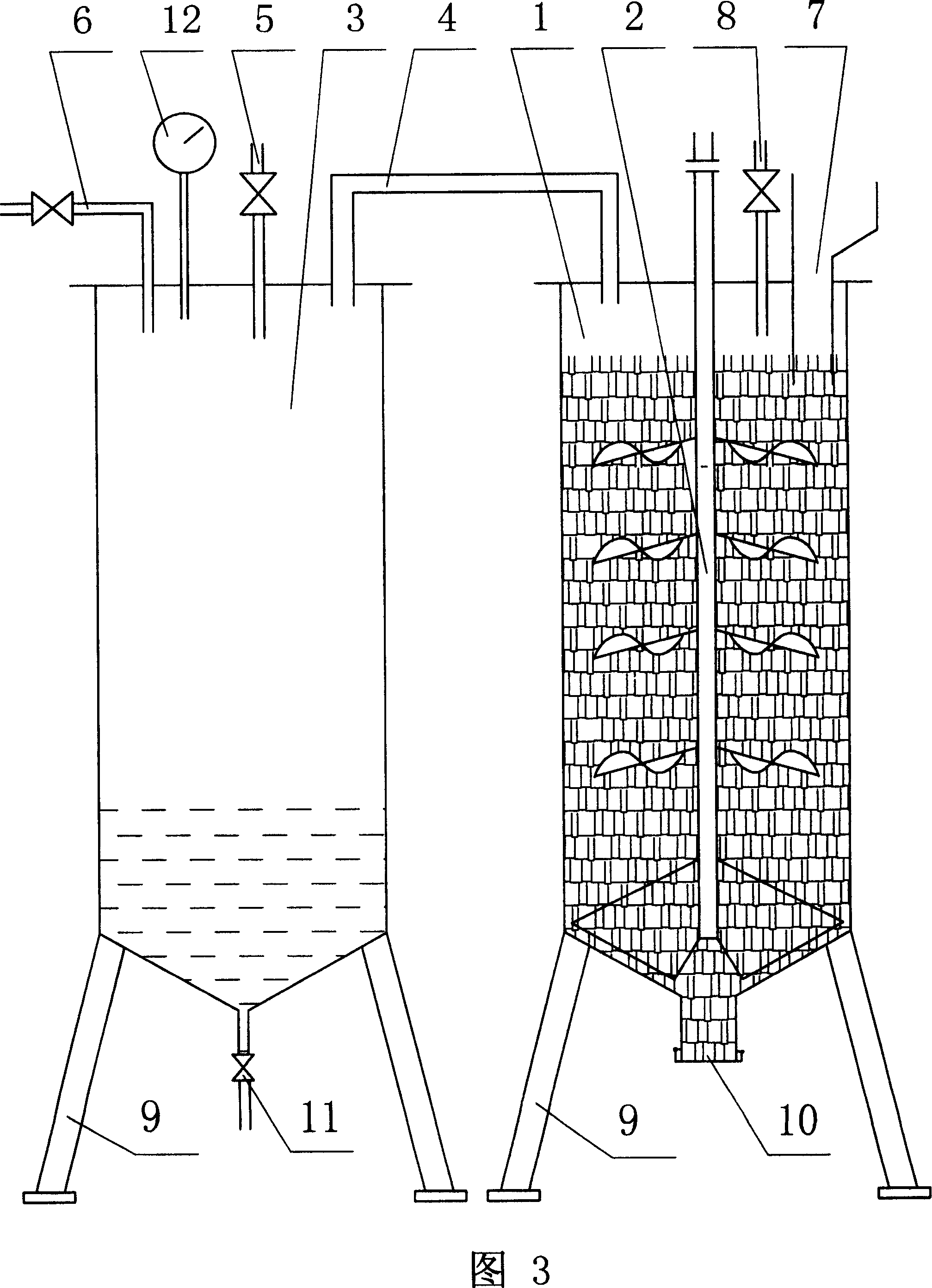
[0023] Figure 3 is a schematic structural diagram of a split-type biogas booster generator; compared with Embodiment 1, its feature is that the pressurization chamber 3 and the generation chamber 1 are separate forms, and the upper ends of the generation chamber 1 and the pressurization chamber 3 It is connected through air duct 4. The bottoms of the generating chamber 1 and the pressurizing chamber 3 are respectively shaped with supporting feet 9, which are movable as a whole. All the other make by embodiment 1.


PUM


Abstract

The present invention discloses a methane pressurizing generator, which has the purpose of providing one kind of the pressurizing generator. Including the generating cavity and the independence pressurizing cavity, two cavities are connected by air pipe, the pressurizing cavity has the water inlet pipe or / and the air inlet pipe, above two cavities with gas outlet pipe connected with the methane apparatus, the generating cavity has charging port and mixer. When the barometric pressure in the pressurizing cavity is excessively low, then pours water or air to the pressurizing cavity, which causes the space of the pressurizing cavity change small, then the methane pressure raises.

Description

technical field [0001] The invention relates to a biogas generator, in particular to a generator capable of pressurizing biogas. Background technique [0002] Biogas is widely used in remote mountainous areas and rural areas, but currently known biogas generators have slow gas production speed and low pressure, and it is difficult to pressurize the produced gas. Most of them are used according to the pressure of biogas output, so the pressure The stability is poor, and the gas production per unit time is small, which affects the normal use of biogas appliances. In addition, general biogas generators are built underground, occupying a small area and low cost. Although it is convenient to feed materials, it is very troublesome to discharge materials. Biogas generators cannot be mass-produced and popularized, which also affects the stability of manufacturing quality. sex. Contents of the invention [0003] The purpose of the prese...

Claims


Application Information

Patent Timeline
Patent Type & Authority Patents(China)
IPC IPC(8): C12M1/107
CPCY02E50/343Y02E50/30
Inventor 王海金
Owner 王海金
Why Eureka
Try Eureka