Two-freedom parallel-connecting mechanism with passive constrained branch

A passive constraint, degree of freedom technology, used in manipulators, manufacturing tools, program-controlled manipulators, etc., can solve problems such as poor lateral load bearing capacity and inability to meet dynamic stiffness requirements, and achieve improved lateral bearing capacity, bearing capacity/ The effect of the mechanism's high weight ratio and large working space

Inactive Publication Date: 2007-10-24
ZHEJIANG UNIV OF TECH
View PDF4 Cites 3 Cited by
  • Summary
  • Abstract
  • Description
  • Claims
  • Application Information

AI Technical Summary

Problems solved by technology

[0004] In order to overcome the deficiencies in the prior art that the parallel mechanism with few degrees of freedom has poor lateral load bearing capacity and cannot meet the requirements of dynamic stiffness in the processing process, the present invention provides a parallel mechanism that can eliminate the spatial singularity to a certain extent. A two-degree-of-freedom parallel mechanism with passive constrained branches with high stiffness, adjustable and high precision

Method used


Image

  • Two-freedom parallel-connecting mechanism with passive constrained branch
  • Two-freedom parallel-connecting mechanism with passive constrained branch
  • Two-freedom parallel-connecting mechanism with passive constrained branch

Examples


Embodiment 1

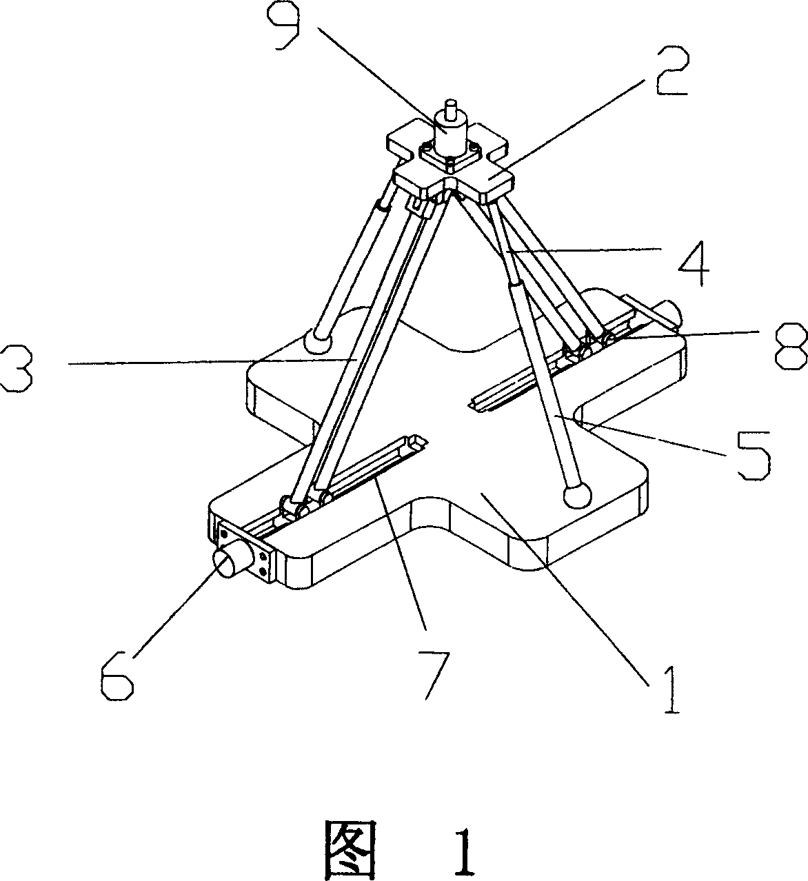
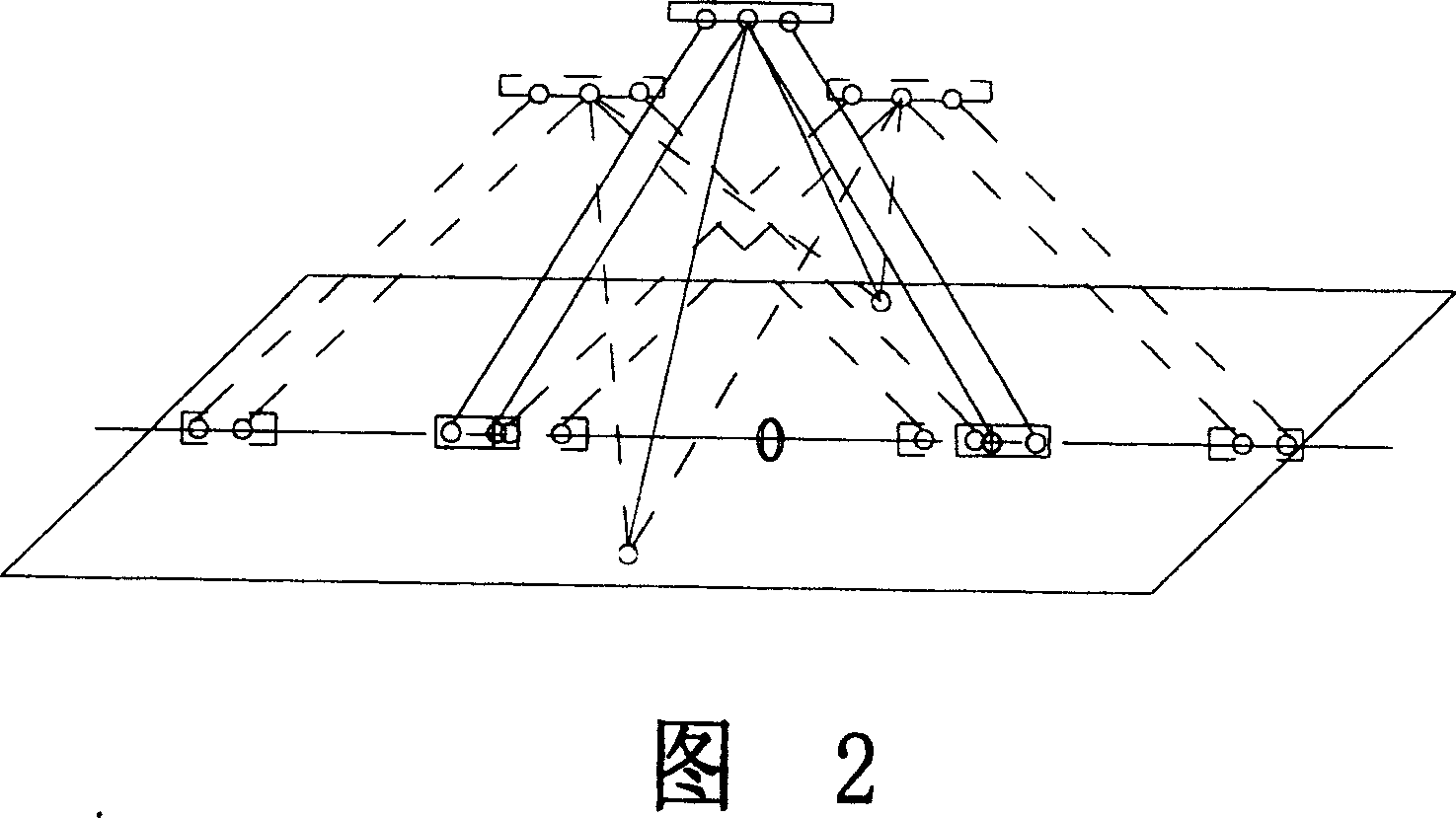
[0018] Referring to Figures 1 and 2, a two-degree-of-freedom parallel mechanism with passive restraint branches includes a static platform 1 and a dynamic platform 2, the static platform 1 is parallel to the dynamic platform 2, the static platform 1 and the The moving platform 2 is connected by two sets of fixed-length active branches 3 and two scalable passive restraint branches. The plane where the two sets of active branches 3 are located is perpendicular to the plane where the two passive restraint branches are located. It is scattered from the moving platform 2 to the static platform 1. Two groups of active branches 3 are equal in length, and each group of active branches is made up of two fixed-length rods. The two passive restraints are also equal in length, and each passive restraint branch is composed of a telescopic rod 4 and a sleeve rod 5, and both of them adopt electromagnetic controllable damping rods, and electromagnetic controllable damping rods are installed i...

Embodiment 2

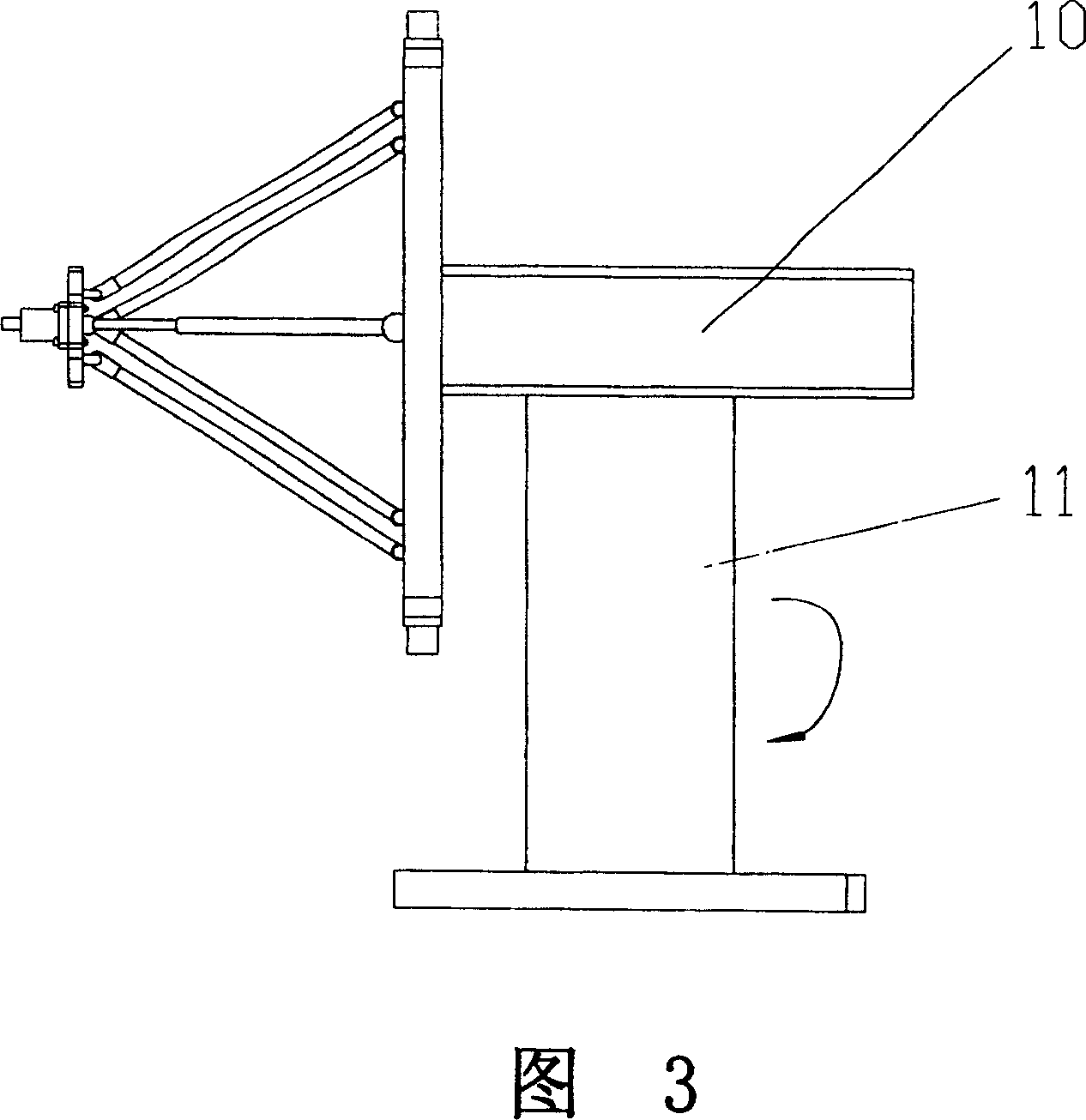
[0022] Referring to Figure 3, the two-degree-of-freedom parallel mechanism with passive restraint branches described in Embodiment 1 is applied to a hybrid robot:

[0023] The two-degree-of-freedom parallel mechanism with passive restraint branches described in Embodiment 1 is used as a module and placed on the connecting frame 10 and the rotating platform 11 . The rotary platform 11 can have various forms, such as: the rotary platform moves along the vertical direction, adjusts the working height of the two-degree-of-freedom parallel mechanism, or the rotary platform rotates around the axis of its own column.

Embodiment 3

[0025] Referring to Figure 4, the two-degree-of-freedom parallel mechanism with passive constraint branches described in Embodiment 1 is applied to a hybrid robot:

[0026] The two-degree-of-freedom parallel mechanism with passive restraint branches described in Embodiment 1 is fixed on the vertical sliding table 12, and the vertical sliding table 12 moves in the horizontal direction to expand the working range, and overcome the parallel problem by rationally planning the moving path of the vertical sliding table 12. There are disadvantages such as small working space and limited posture of the mechanism.


PUM


Abstract

A two-freedom parallel mechanism with passive constraint branches is composed of movable platform, static platform with slots and parallel to movable platform, the two groups of length-fixed active branches and two telescopic passive constraint branches for linking both platforms, and the leading screws with serve motor and slide block and arranged in said slots on static platform. Said active branches and passive constraint branches are linked with both platforms respectively via pin and slide block or ball socket. Its advantages are high lateral load bearing power and no couple between active and passive branches.

Description

(1) Technical field [0001] The invention belongs to the field of robot and mechanical manufacturing, and in particular relates to a two-degree-of-freedom parallel mechanism with passive constraint branches. (2) Background technology [0002] In recent years, space parallel robots have aroused widespread interest of scholars at home and abroad. Compared with series robots, parallel robots have the characteristics of high rigidity, high load-to-weight ratio, small inertia, and no accumulation of position errors. The earliest parallel robot with six degrees of freedom in space is based on the 6-SPS mechanism proposed by Stewart in 1965. In order to enrich and develop the structural forms of parallel robots, scholars in many research institutions have done a lot of useful work. The development of robots proposes to use cheap and simple parallel robots with few degrees of freedom. In recent years, some parallel mechanisms with few degrees of freedom have become new research ho...

Claims


Application Information

Patent Timeline
Patent Type & Authority Patents(China)
IPC IPC(8): B25J9/08
CPCB25J9/0072
Inventor 王忠飞计时鸣王扬渝袁巧玲艾青林张宪欧长劲朱根兴金明生
Owner ZHEJIANG UNIV OF TECH
Why Eureka
Try Eureka