Tow cutter

A cutter and tow technology, which is applied in the direction of fiber bundle to fiber sliver/yarn, etc., can solve the problems of clamping knife and tow not being able to cut 100% to achieve quality assurance, scientific and reasonable cutting edge curve, and highlight substantive features Effect

Inactive Publication Date: 2007-10-24
周卫明
View PDF6 Cites 0 Cited by
  • Summary
  • Abstract
  • Description
  • Claims
  • Application Information

AI Technical Summary

Problems solved by technology

Therefore, when the shaft-shaped knife is pushed forward under the action of the cylinder, the cutting edge of the intersecting elliptic curve actually has a tendency to push the tow outward, that is, to the unsharp part of the cutting edge (see Figure 1B), and the result As a result, the tow cannot be cut 100%, and even a small amount of tow will be squeezed into the gap in severe cases, resulting in the phenomenon of "knife clamping"

Method used


Image

  • Tow cutter
  • Tow cutter
  • Tow cutter

Examples


Embodiment 1

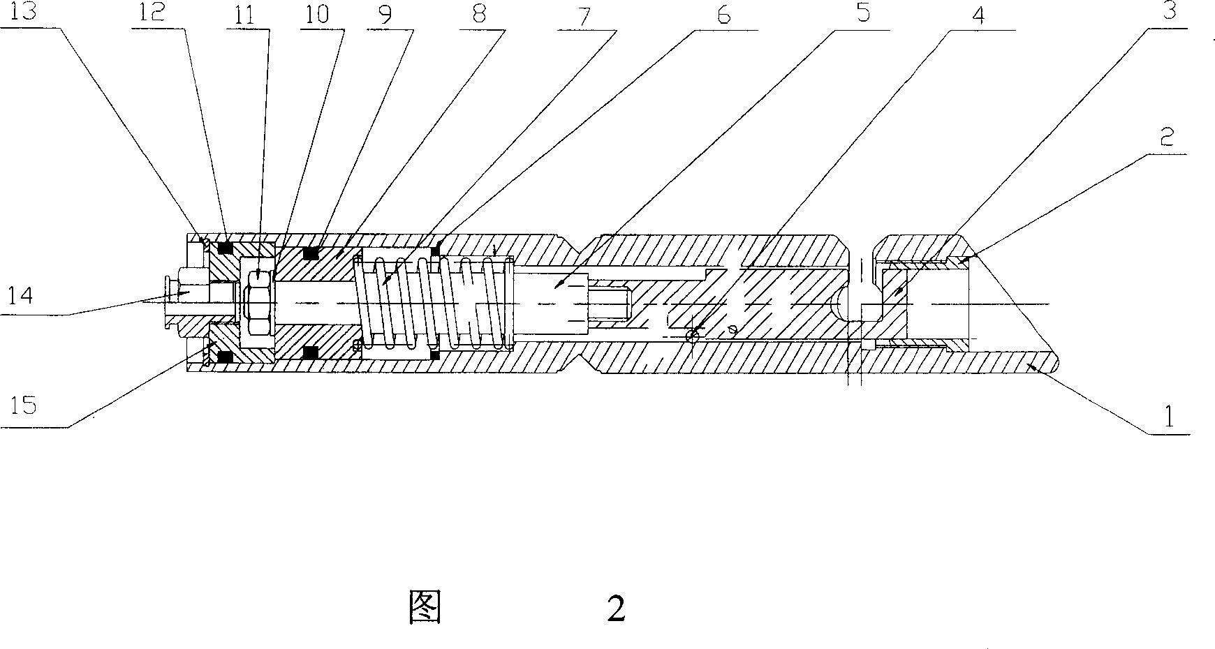
[0014] The tow cutter of this embodiment is shown in FIG. 1 , and a ring knife 2 is press-fitted and fixed in the stepped hole at the front end of the tubular housing 1 . The rear end of the shaft-shaped knife 3 is fixedly connected with the cylinder shaft 5 through threaded connection, and is installed in the housing by sliding fit. The cylinder shaft 5 rear end is a spring 7, a piston 8, a joint 14, and a rear plug 15 forming a cylinder assembly with it. All the other parts 6 are gaskets, 9 are O-rings, 10 gaskets, 11 are nuts, 12 are O-rings, and 13 are inner retaining rings, which play sealing and fastening connections respectively. Since the structure of the cylinder assembly is the same as the known technology, it will not be described in detail.

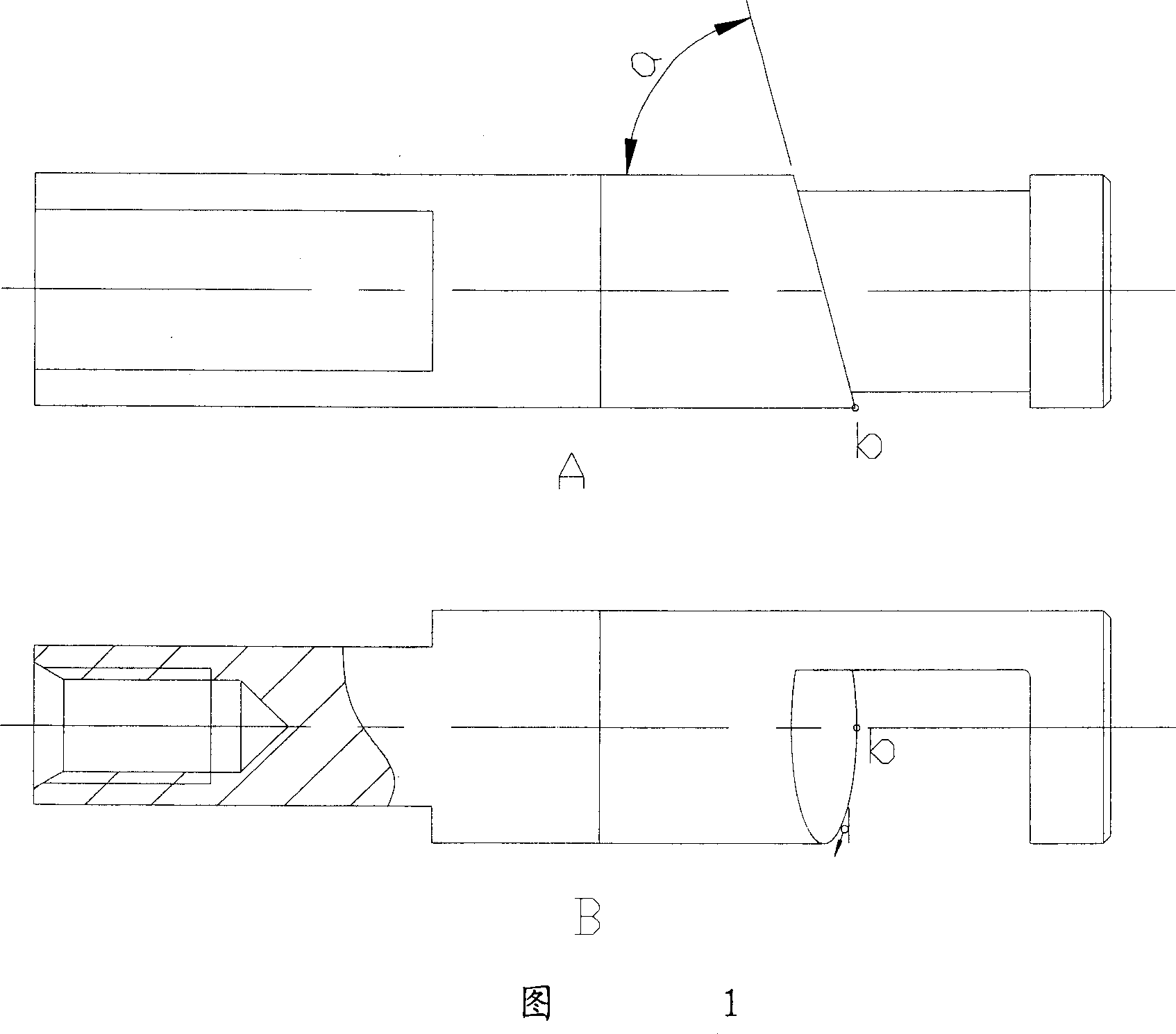
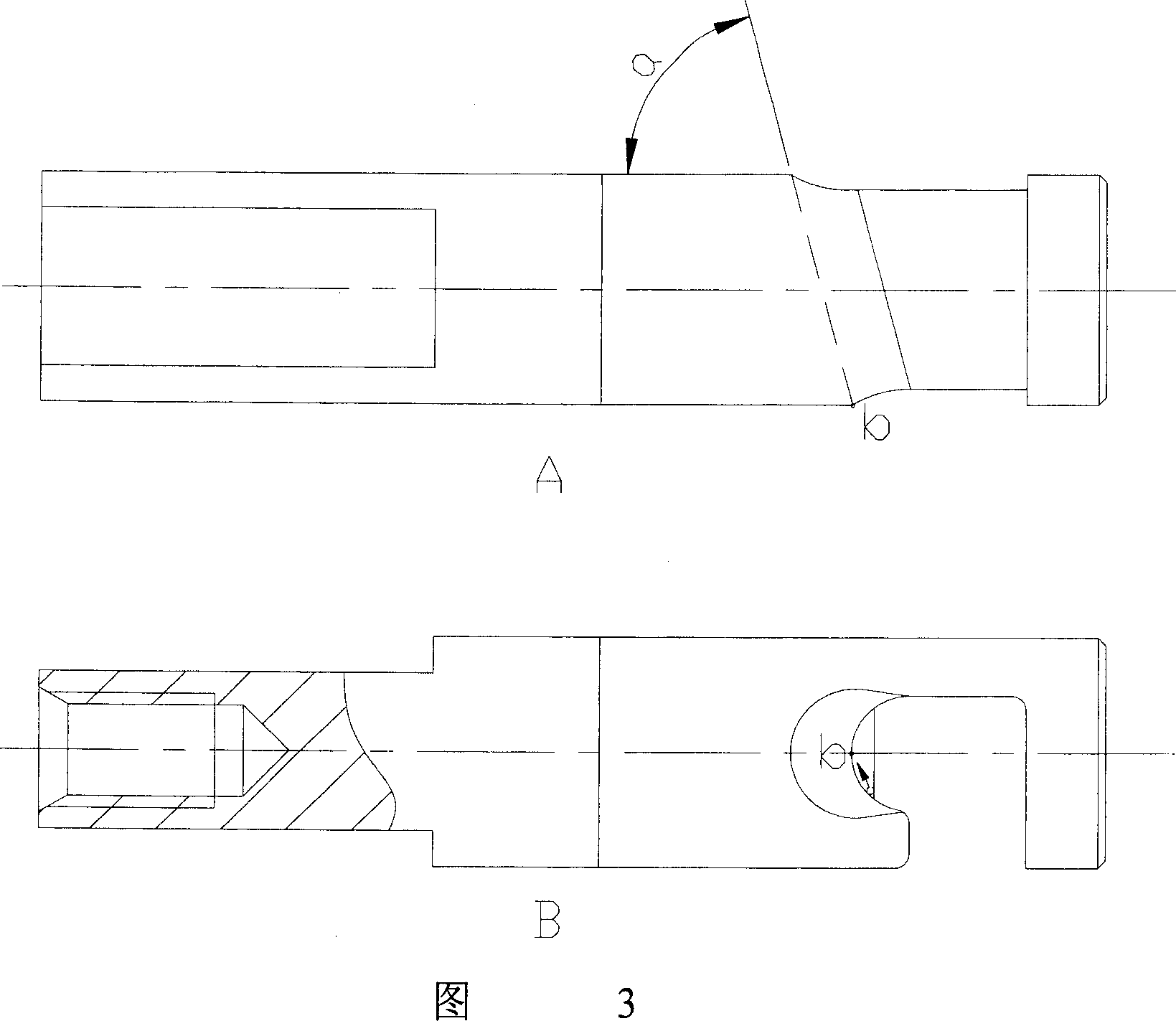
[0015] The concrete structure of shaft-shaped cutter 3 is as shown in Figure 3, and the front end is shaped on breach, and the cutting edge of shaft-shaped cutter is formed by the inner concave conical surface of acute angle ...


PUM

PropertyMeasurementUnit
angleaaaaaaaaaa
angleaaaaaaaaaa

Abstract

The invention relates to a development of the structure of string cutter, belonging to the chemical fiber mechanical technique field. The string cutter is mainly comprised of pipe-shaped shell. annular knife, axiual-shaped knife and cylinder, the annular knife is fixed in the front of the shell, the back of axiual-shaped knife is connected with the axiual of cylinder, and its circle outside is matched with the inner hole of annular knife and placed in the shell. The front of axiual-shaped knife has gap, and the developments include: the cutting edge is formed by the inner concave curved surface with acute angle (cylindrical face) to the axual line and the outer acute angle (cylindrical face), considering the manufacturing technique, the inner concave curved surface should use the cylinder or conical surface with acute angle (cylindrical face) to the axiual line. By using the structure of axual-shaped knife, there is the tendency of string assembling inside and the sharpest part of cutting edge when the curve of cutting edge meets the annular cutting edge of the annular knife, which can assure the string being cur off completely the quality of the presteps and supply the convenience for the subseqent handling.

Description

technical field [0001] The invention relates to a chemical fiber tow cutting device, in particular to a structural improvement of a tow cutter, which belongs to the technical field of chemical fiber machinery. Background technique [0002] The tow cutter is usually used in the pre-spinning process of the chemical fiber industry, and its function is to cut about 5,000 fiber tows formed after hanging yarn at one time. [0003] The existing tow cutter is mainly composed of a tubular housing, an annular knife, a shaft-shaped knife and a cylinder shaft. Wherein, the annular knife is fixed on the front end of the housing, the rear end of the shaft-shaped knife is fixedly connected with the cylinder shaft, and is installed in the housing by sliding fit. As shown in Figure 1A and Figure 1B of the shaft-shaped knife, the front end is shaped with a gap, and the cutting edge of the knife is formed by an intersecting elliptic curve formed by an inclined plane with an angle a to the axi...

Claims


Application Information

Patent Timeline
Patent Type & Authority Patents(China)
IPC IPC(8): D01G1/10
Inventor 徐钦元
Owner 周卫明
Why Eureka
Try Eureka