High branch pruning device for garden

A pruning device and high branch technology, applied in the field of high branch pruning devices for gardens, can solve the problems of labor, shortening the continuous working time of pruning personnel, and increasing the cleaning workload of pruning personnel, so as to increase the workload, ensure smoothness, and speed up cutting. The effect of the rate

Inactive Publication Date: 2020-10-16
靳建芹
View PDF22 Cites 0 Cited by
  • Summary
  • Abstract
  • Description
  • Claims
  • Application Information

AI Technical Summary

Problems solved by technology

But the existing high-branch pruning shears are in the process of pruning and cutting leaves, and the cut branches and leaves are scattered everywhere, which greatly increases the cleaning workload of the pruning personnel, and when larger branches are pruned, it is more laborious and greatly Reduced duration of pruning personnel

Method used


Image

  • High branch pruning device for garden
  • High branch pruning device for garden
  • High branch pruning device for garden

Examples


Embodiment 1

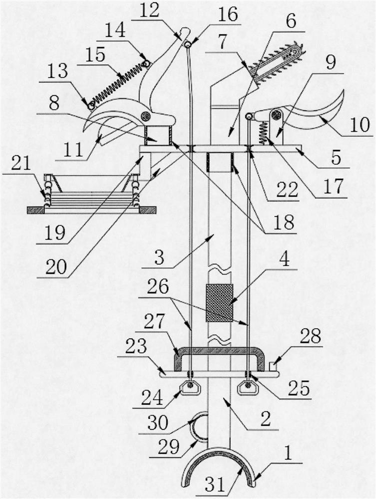
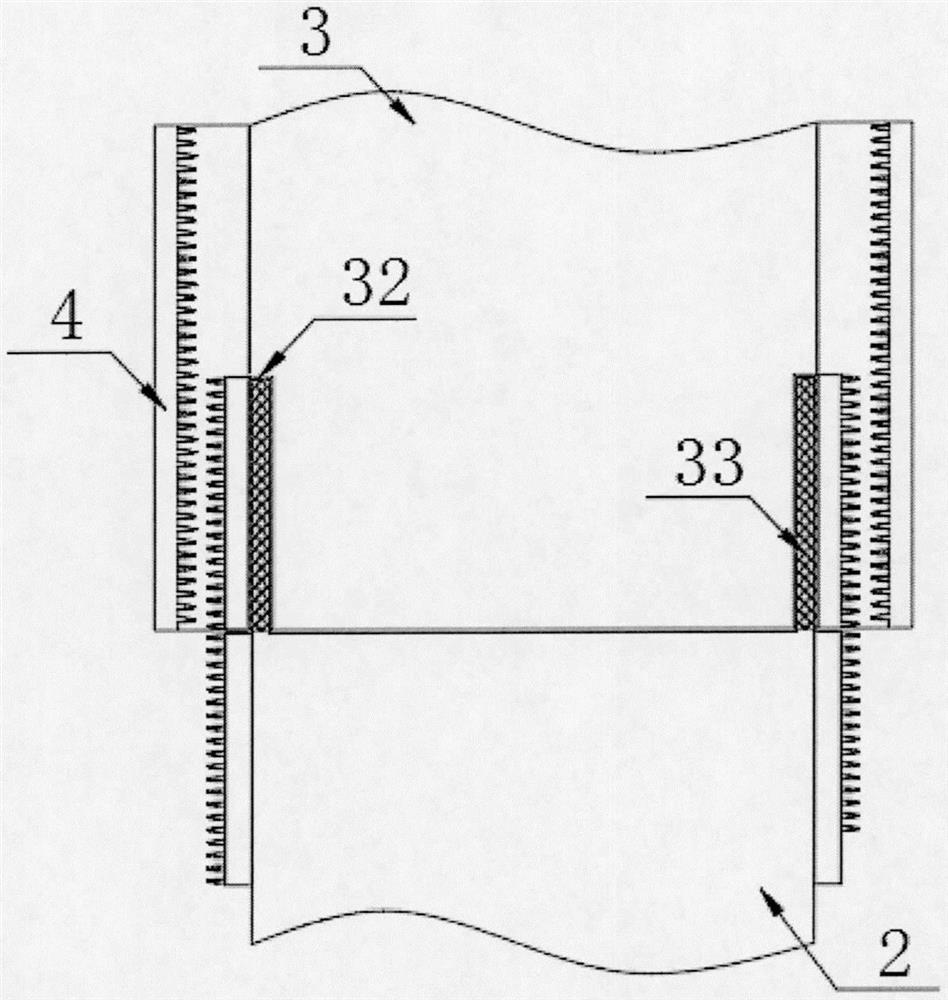
[0031] The present invention provides such Figure 1-6The high-branch pruning device shown in the garden comprises a base 1, a first pole 2 is arranged on the top of the base 1, a second pole 3 is arranged on the top of the first pole 2, and a second pole 3 is arranged on the top of the first pole 2. A connecting sleeve 4 is provided at the joint between the pole 2 and the second pole 3, a top plate 5 is provided on the top of the second pole 3, a power supply 6 is provided at the top middle of the top plate 5, and a power supply 6 is provided at the top of the power supply 6 There is a sawing mechanism 7, a first column 8 is provided on one side of the power supply 6 and a second column 9 is provided on the other side, and a first cutter 10 is provided on the top of the first column 8 and the second column 9 , the bottom of the first cutter 10 at the top of the first column 8 is equipped with a second cutter 11, and one end of the second cutter 11 is fixedly connected with a ...

Embodiment 2

[0038] Further, in the above technical solution, a reinforcing rod 20 is inclined between the connecting rod 19 and the top plate 5, so that a triangular frame is formed between the connecting rod 19, the reinforcing rod 20 and the top plate 5, thereby greatly improving the material guiding mechanism. 21 Stability during use.

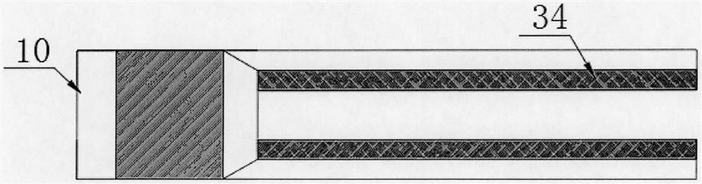
[0039] Further, in the above technical solution, the first cutter 10 is provided with a cutter head 34, the number of the cutter head 34 is provided with two, and the two cutter heads 34 are in the shape of the central axis of the first cutter 10. Axisymmetrically arranged, the distance between the two cutter heads 34 is equal to the maximum distance between the two transmission chains 77, on the one hand, it can ensure that the branches are cut off completely, and on the other hand, it can ensure the smoothness of the branch incision. The projection shape of the head 34 in the main viewing direction is arc-shaped, and the branches to be pruned can be s...


PUM


Abstract

The invention discloses a high-branch trimming device for a garden. The high-branch trimming device comprises a base, a first supporting rod is arranged at the top of the base, a second supporting rodis arranged at the top of the first supporting rod, a connection sleeve is arranged at a joint of the first supporting rod and the second supporting rod, a top plate is arranged at the top of the second supporting rod, a power supply is arranged in the middle of the top plate, a sawing mechanism is arranged at the top of the power supply, a first upright and a second upright are arranged on two sides of the power supply respectively, and a first cutter is arranged at the top of each of the first upright and the second upright. A contractile guide mechanism is utilized to guide cut-down branches and leaves, so that the high-branch trimming device is suitable for trimming needs different in height, and can ensure falling branches and leaves to stably fall on the ground, thereby being convenient for cleaning; motors opposite in running direction are utilized to drive two transmission chains with inclined arc-shaped sawteeth to rotate in opposite directions, so that speed in cutting big branches is greatly increased.

Description

technical field [0001] The invention relates to the field of garden pruning equipment, in particular to a high-branch pruning device for gardens. Background technique [0002] High branch pruning shears are a common tool for garden maintenance. They are usually used to prune and cut leaves on the high branches of trees to make their appearance more beautiful or to facilitate their growth. But the existing high-branch pruning shears are in the process of pruning and cutting leaves, and the cut branches and leaves are scattered everywhere, which greatly increases the cleaning workload of the pruning personnel, and when larger branches are pruned, it is more laborious and greatly The continuous working time of pruning personnel has been shortened. [0003] Therefore, it is necessary to invent a kind of high-branch pruning device for gardens to solve the above problems. Contents of the invention [0004] The object of the present invention is to provide a high-branch pruning...

Claims


Application Information

Patent Timeline
Patent Type & Authority Patents(China)
IPC IPC(8): A01G3/025A01G3/08
CPCA01G3/0251A01G3/0255A01G3/085A01G3/086
Inventor 靳建芹赵海祥李彦民武云飞肖海霞刘向娜
Owner 靳建芹
Why Eureka
Try Eureka