Permanent magnet synchronous motor for shielded pump

A permanent magnet synchronous and motor technology, applied in the field of motors, can solve the problems of no shielding sleeve and inability to achieve shielding in the motor, and achieve the effects of less magnetic leakage, simple structure and strong overload capacity.

Inactive Publication Date: 2007-10-24
SHENYANG POLYTECHNIC UNIV
View PDF4 Cites 1 Cited by
  • Summary
  • Abstract
  • Description
  • Claims
  • Application Information

AI Technical Summary

Problems solved by technology

This kind of motor has strong pull-in synchronization ability, and its power factor and efficiency have been improved, but there is no shielding sleeve inside the motor, so the shielding effect cannot be achieved

Method used


Image

  • Permanent magnet synchronous motor for shielded pump
  • Permanent magnet synchronous motor for shielded pump
  • Permanent magnet synchronous motor for shielded pump

Examples


Embodiment Construction

[0013] Further describe content of the present invention below in conjunction with accompanying drawing and embodiment:

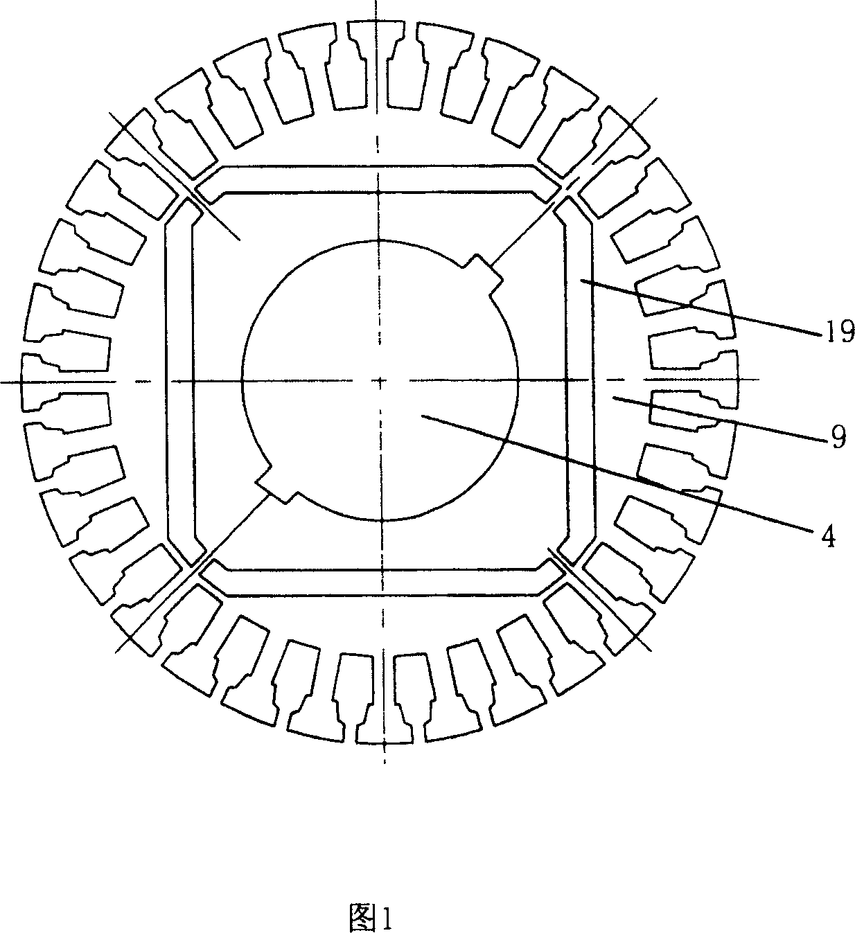
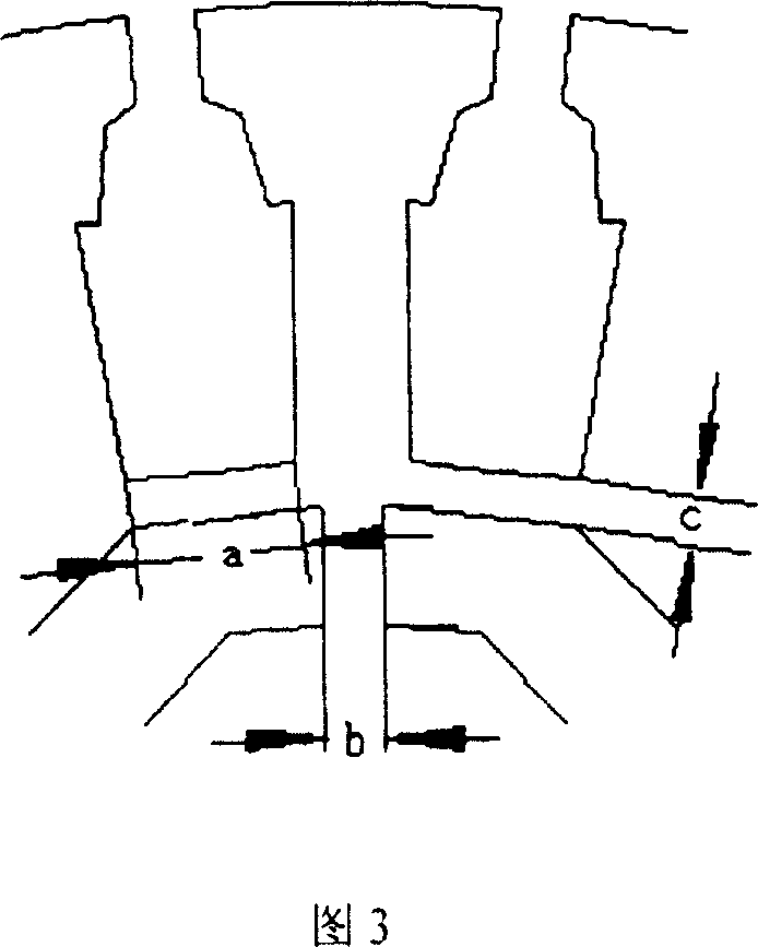
[0014] In the mechanical structure of the present invention, the rotor core 9 is provided with a permanent magnet 10 inside, and the other structures are the same as those of the squirrel-cage induction motor. As shown in Figure 3: it includes the front bearing chamber 1, the rear bearing chamber 18 and the bearing 15 and bearing sleeve 16 inside, the shaft 4, the rotor, and the stator. Sleeve 6, rotor core 9, rotor baffle 12, auxiliary impeller 13, also includes permanent magnet 10, permanent magnet baffle 11, inside the rotor core 9 there is a permanent magnet groove 19 along the radial direction, and the permanent magnet 10 is embedded in the permanent magnet groove In 19 (rotor stamping figure as shown in Figure 1), fix with permanent magnet baffle plate 11; Permanent magnet groove 19 is positioned at rotor groove inside, and there is magnetic isolation...


PUM


Abstract

The permanent magnet synchronous motor for shield pump belongs to motor technique field, which comprises backward and forward bearing rooms with interior bearing, bearing housing, shaft, rotor and stator with rotor shield sleeve, iron core, baffle and auxiliary blade wheel, and permanent magnet and its baffle; wherein, cutting permanent magnet slot in rotor iron core along rotation shaft tangent; embedded the permanent magnet in slot and fixed with said baffle; the permanent magnet slot is in rotor slot with magnetic bridge for separation. This invention overcomes shortcoming of existing motor, increases efficiency and power, simplifies structure, and fits to running for long time.

Description

technical field [0001] The invention relates to the technical field of motors, in particular to a permanent magnet synchronous motor used for canned pumps. Background technique [0002] At present, induction motors widely used in petroleum, chemical industry, light industry, and pharmaceutical industries have a structure including front and rear bearing chambers and internal bearings and bearing sleeves, shafts, rotors and rotor shielding sleeves, stators and stator shielding sleeves. The effect of shielding is to prevent substances such as corrosive, highly toxic, radioactive, flammable and explosive, volatile and high-temperature liquids from being exposed at all. However, due to the shielding sleeve inside the motor, the air gap of the motor is large, making the motor The power factor and efficiency are lower than the induction motor of the same specification, and the rated current is large, so the effect of energy saving cannot be achieved. The permanent magnet synchron...

Claims


Application Information

Patent Timeline
Patent Type & Authority Patents(China)
IPC IPC(8): H02K1/27H02K15/03H02K1/02
Inventor 唐任远安忠良马鑫赵清
Owner SHENYANG POLYTECHNIC UNIV
Why Eureka
Try Eureka