Reactor for catalytic reaction research

A catalytic reaction and reactor technology, applied in the field of reactors, can solve the problems of large free space, difficult to use, and no reaction results, and achieve the effects of reducing the evaluation period, wide application range and long service life

Active Publication Date: 2007-10-31
SYNFUELS CHINA TECH CO LTD
View PDF2 Cites 0 Cited by
  • Summary
  • Abstract
  • Description
  • Claims
  • Application Information

AI Technical Summary

Problems solved by technology

[0003] However, the fixed bed reactor has the following disadvantages: (1) For catalysts with larger particles, due to the large gap between the reactor tube wall and the particles, a part of the reactants flow out along the tube wall without contacting the catalyst, so that the real catalyst cannot be obtained. The result of the reaction
[0008] (1) Since there are only two or four baskets, the loading capacity of the catalyst is limited, and only a small amount of catalyst can be loaded, which prolongs the selection cycle of the catalyst
[0009] (2) There are only two or four baskets, so the free space in the reactor is too large, and it is not easy to use in the reaction where the free space affects the reaction process
The heavy components that are easy to solidify will solidify in the casing, which will hinder the normal rotation of the stirring shaft, so it is not suitable for reactions containing heavy components in the product, such as Fischer-Tropsch synthesis reactions
[0014] (2) Since the motor and the transmission device are in the lower part of the reactor, if there is a problem with the motor and the transmission device, the reaction has to be stopped and the reactor is removed for processing, which will interrupt the long-term operation experiment for evaluating the life of the catalyst

Method used


Image

  • Reactor for catalytic reaction research
  • Reactor for catalytic reaction research
  • Reactor for catalytic reaction research

Examples


Embodiment Construction

[0028] The present invention will be described in detail below with reference to the accompanying drawings.

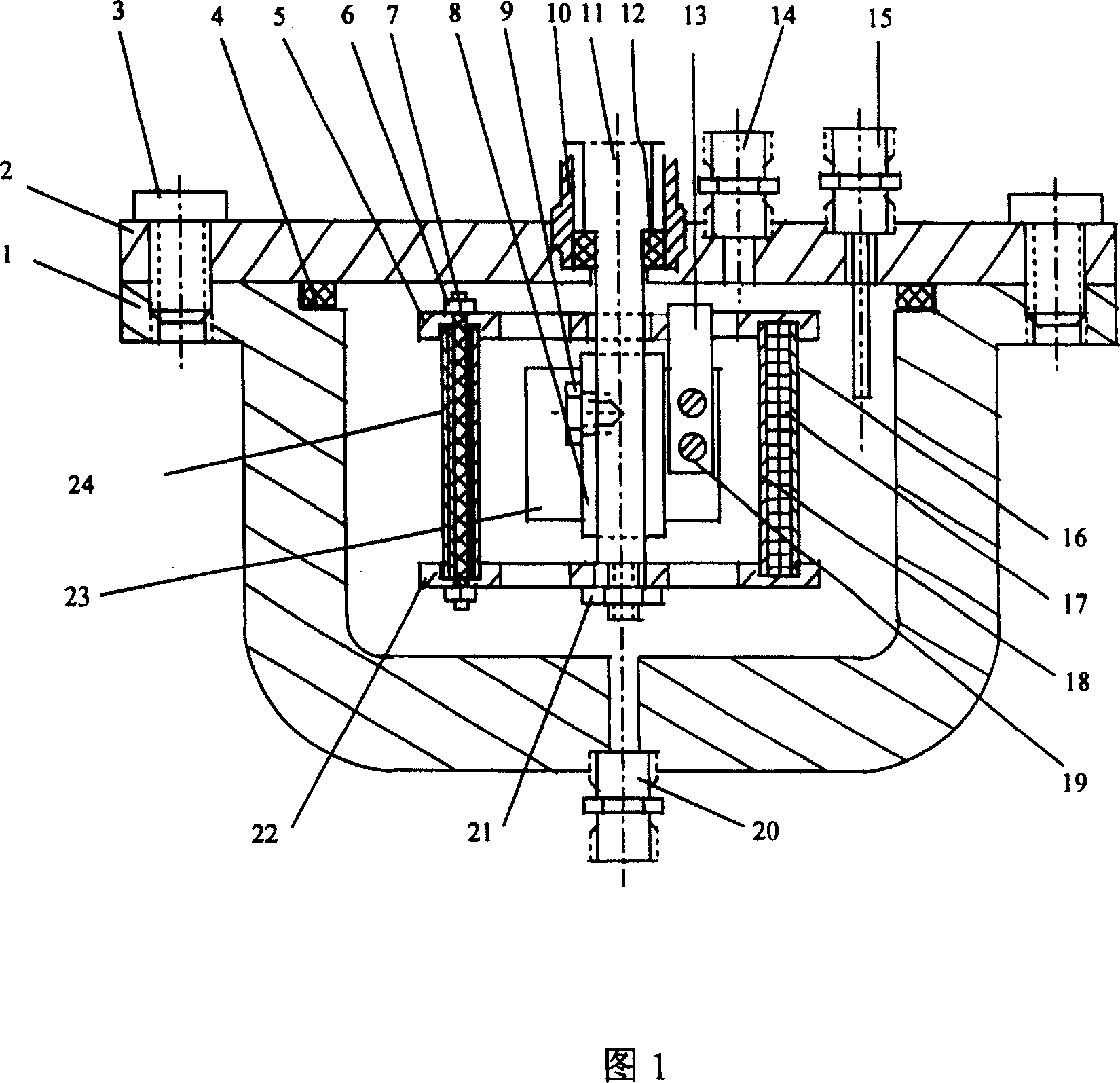
[0029] Figure 1 is a cross-sectional view of the reactor of the present invention.

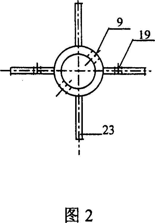
[0030] Figure 2 is a top view of the paddle of the present invention.

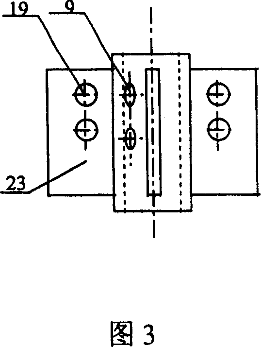
[0031] Figure 3 is a side view of the paddle of the present invention.

[0032] Figure 4 is a structural cross-sectional view of the connector in the reactor of the present invention.

[0033] Fig. 5 is a structural cross-sectional view of the upper pressing plate of the present invention.

[0034] Figure 6 is a structural cross-sectional view of the lower pressing plate of the present invention

[0035] As shown in the figure, the U-shaped kettle body 1 and the kettle cover 2 are connected by bolts 3, and the sealing ring 4 between the U-shaped kettle body 1 and the kettle cover 2 is compressed to ensure the sealing of the reactor. There is a motor drive shaft hole in the center of the kettle cover 2 from which the mo...


PUM


Abstract

The invention relates to a reactor for catalytic reaction research. It includes: kettle lid, kettle body, inlet, outlet, temperature measurement port, motor dirve shaft, blade and catalyst swivel. Kettle body is in a U shape. Inlet and temperature measurement port are on top of kettle lid. Outlet is at bottom of kettle body. Motor dirve shaft extrudes into kettle body through kettle lid. Blade is fixed on motor dirve shaft. Catalyst swivel is made up with upper clamping bar, lower clamping bar, inner screen cloth and outer screen cloth. It lies in bosom of kettle body. Inner screen cloth and outer screen cloth lies in middle of upper clamping bar and lower clamping bar which fixes with motor drive shaft. Upper clamping bar connects to blade. The invention can load plenty of catalyst to reduce evaluation period of catalyst. It can be used in reaction containing heavy components with a simple construction and long life.

Description

Technical field: [0001] The invention belongs to a reactor, and specifically relates to a reactor for catalytic reaction research. Background technique: [0002] When conducting research on heterogeneous catalysis in the laboratory, it is usually carried out in a fixed-bed reactor. The catalyst is loaded into the reactor, and the reactants enter from the upper part, flow out from the lower part, and pass through the catalyst bed. Under the action of the catalyst, the reactants are transformed into products. [0003] However, the fixed-bed reactor has the following disadvantages: (1) For catalysts with larger particles, due to the large gap between the reactor tube wall and the particles, a part of the reactants flow out along the tube wall without contacting the catalyst, thus failing to obtain real The result of the reaction. (2) In the study of reaction kinetics, it is necessary to investigate the relationship between reaction components, temperature and reaction rate. The reac...

Claims


Application Information

Patent Timeline
Patent Type & Authority Patents(China)
IPC IPC(8): B01J8/18B01J19/18
Inventor 李永旺张荣乐李伟白亮相宏伟周敬来
Owner SYNFUELS CHINA TECH CO LTD
Why Eureka
Try Eureka