
Method to reduce power in a computer system with bus master devices

A technology of bus master control and equipment, applied in the field of power management

Inactive Publication Date: 2007-11-28
INTEL CORP
View PDF9 Cites 0 Cited by
  • Summary
  • Abstract
  • Description
  • Claims
  • Application Information

AI Technical Summary

Problems solved by technology

However, if something triggers a cache coherency problem, and it happens as often as the preemption interval, the processor will never enter the C3 state

Method used


Image

  • Method to reduce power in a computer system with bus master devices
  • Method to reduce power in a computer system with bus master devices
  • Method to reduce power in a computer system with bus master devices

Examples


Embodiment Construction

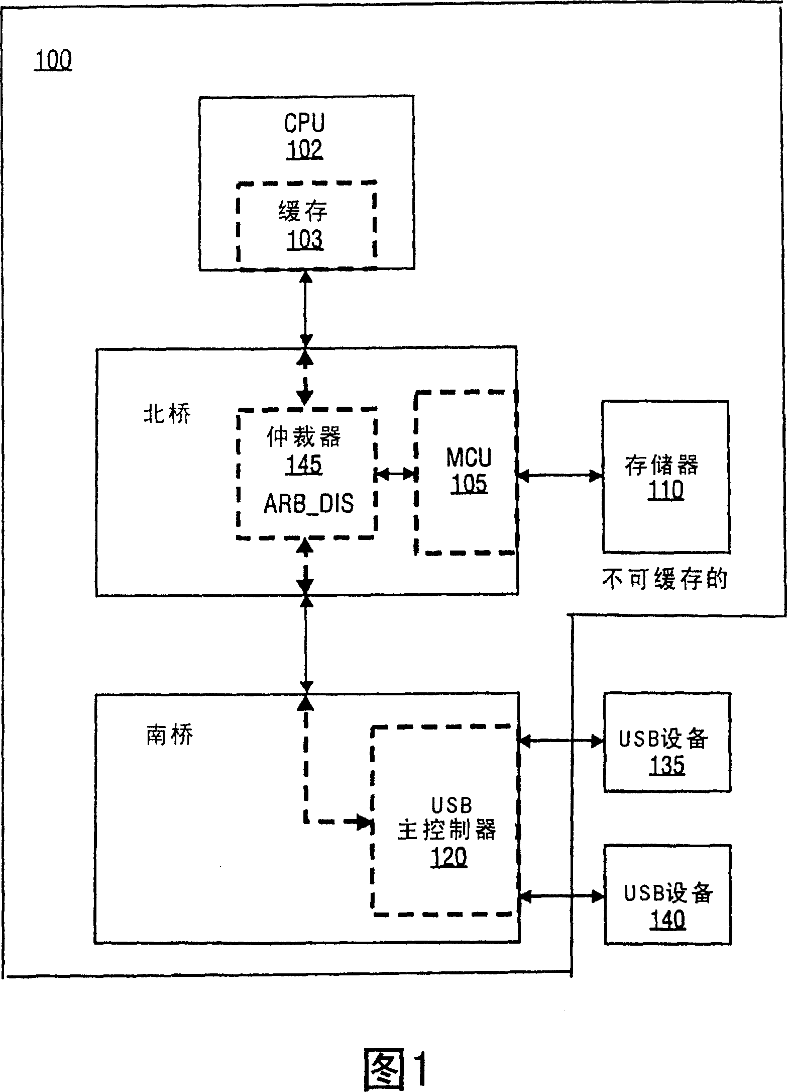
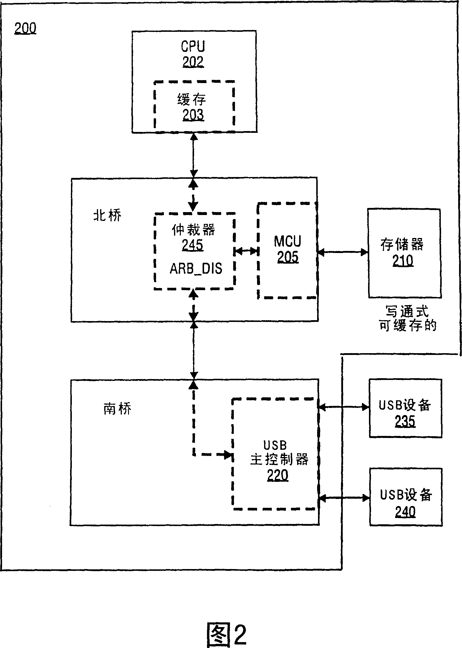
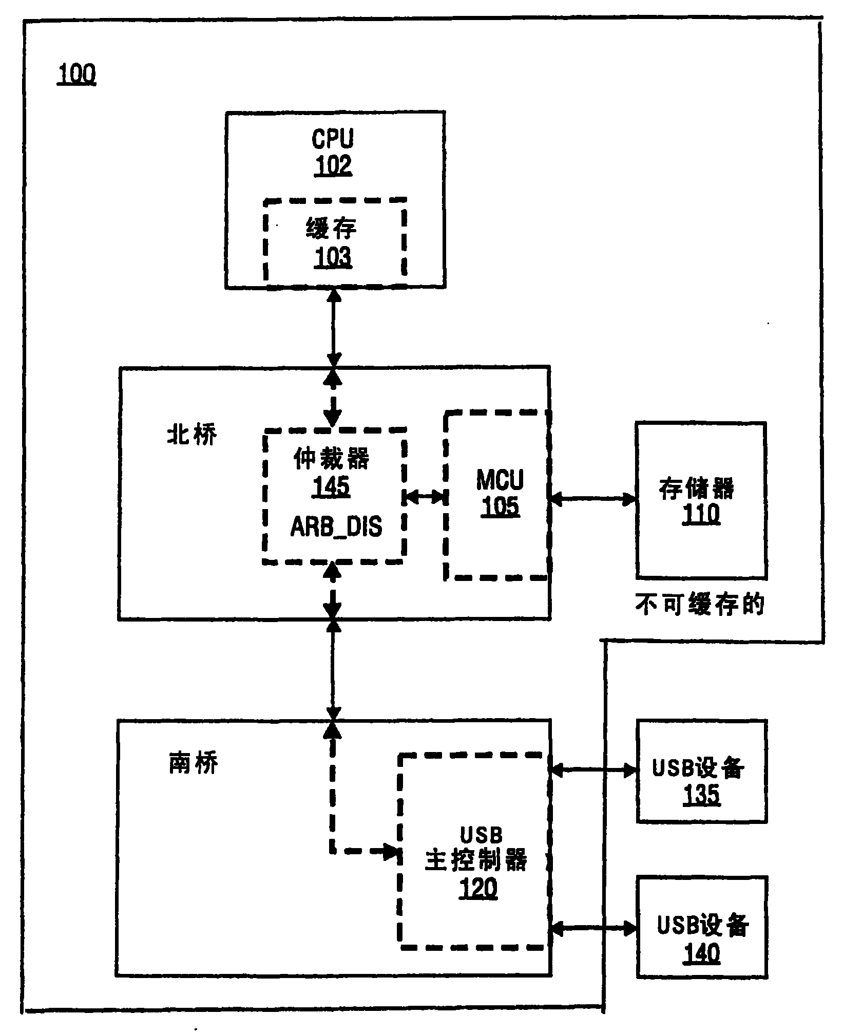
[0013] In one embodiment, a method is disclosed that avoids setting the BM STS bit to cause the processor to enter the C3 state while maintaining memory coherency. By changing the caching policy of the bus master buffer, many bus master activities can be done without cache coherency issues, thus eliminating the need for tracking of the BM_STS bit, allowing the processor to enter the C3 state more often.

[0014] In the following description, for purposes of explanation, numerous specific details are set forth in order to provide a thorough understanding of the present invention. It will be apparent, however, to one skilled in the art that the present invention may be practiced without these specific details. Also, in order to avoid unnecessary detail in the explanation, some well-known structures, procedures and devices are shown in block diagram form and are referenced in general terms.

[0015] Typically, a bus mastering status (BM_STS) bit is set with a bus mastering read ...


PUM


Abstract

A system memory (110, 210) accessed by a bus master controller (145, 245) is set as non-cacheable. A bus master status bit is not set for any bus master controller transfer cycles with the non-cacheable memory while the system processor (102, 202) is in a low power state.

Description

technical field [0001] The present invention relates generally to the field of power management. More specifically, the present invention relates to methods and systems for causing a processor to enter a low power state. Background technique [0002] The hardware and software environment defined by the Advanced Configuration and Power Interface (ACPI) specification enables operating system (OS) software to achieve visibility and control of system configuration and power management. ACPI combines power management and plug-and-play functionality for computer systems. ACPI describes a set of valid processor operating states and the transitions allowed between these states. The first four states defined for the processor are C0, C1, C2 and C3. The C0 state is a normal working state. The C1 state is a low-power, low-latency state that does not require any support from the chipset logic and retains all cached context. The C2 state is a lower power and slightly longer latency ...

Claims


Application Information

Patent Timeline
IPC IPC(8): G06F1/32G06F12/08
CPCY02B60/1225G06F12/0835G06F1/3203G06F1/3275G06F12/0837Y02D10/00G06F1/26G06F1/32G06F13/16
Inventor 詹姆斯·卡尔达什
Owner INTEL CORP
Learn More