
Compensation method for improving colour saturability and image quality of flat plasma display

A flat-panel display, image quality technology, applied in static indicators, instruments, nonlinear optics, etc., can solve the problems of low light transmittance, negative impact of plasma flat-panel display brightness, and unsatisfactory, and achieve low-cost effects

Inactive Publication Date: 2007-11-28
CPT TECH GRP
View PDF10 Cites 0 Cited by
  • Summary
  • Abstract
  • Description
  • Claims
  • Application Information

AI Technical Summary

Problems solved by technology

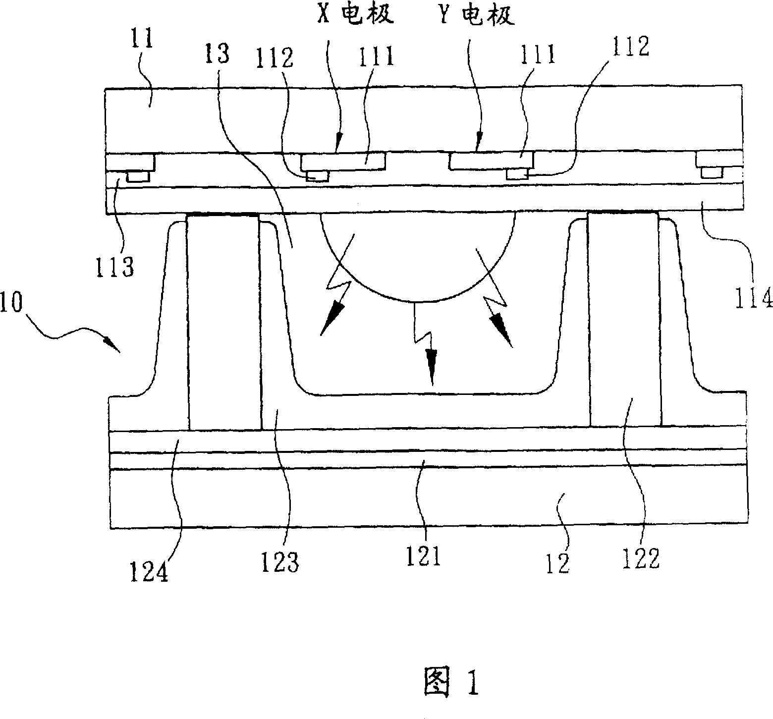
[0003] Because, in the aforementioned conventional plasma flat panel display 10, the back substrate 12 is mainly provided with a plurality of white barrier walls 122 arranged in parallel and uniformly coated phosphors 123, so when the plasma flat panel display 10 is irradiated by ambient light, The white barrier walls 122 and phosphors 123 on the back substrate 12 can easily diffuse the ambient light, causing the problems of color saturation and image quality degradation of the plasma flat panel display 10 in a bright environment.
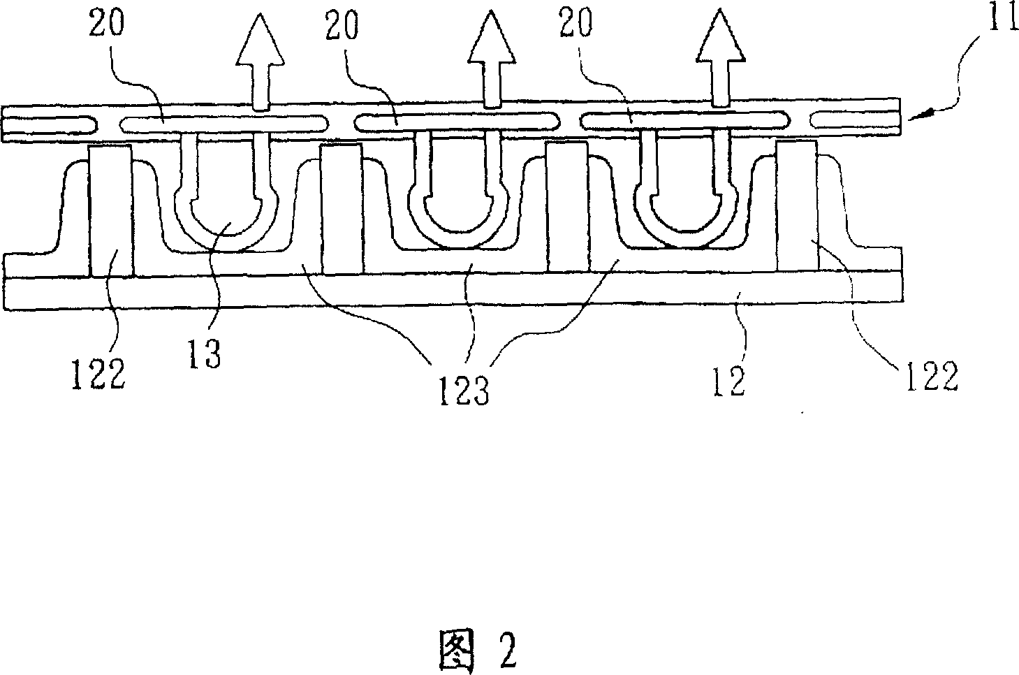
[0004] Traditionally, manufacturers of plasma flat panel displays have designed unique solutions to this problem. Take NEC Corporation of Japan as an example. Corresponding to the positions of the discharge cells 13 such as red (Red), green (Greed) and blue (Blue), respectively add a filter film 20, as shown in FIG. 2, to filter out high brightness ambient light for each discharge cell The anti-color light produced by 13 can effectively improve the color saturation of plasma flat-panel displays in bright ambient spaces, but the processing technology of adding color filter film 20 is cumbersome, so the manufacturing cost of plasma flat-panel displays has been greatly increased; and the Japanese Plasmaco company A circular polarizing filter is used to suppress the influence of high-brightness ambient light, but since the light transmittance of the circular polarizing filter is too low, it will have a negative impact on the brightness of the plasma flat-panel display itself. Therefore, this approach is obviously not ideal
[0005] It can be seen from the above that the traditional methods only use the method of adding filter elements to try to filter out the reflected color light generated by the high-brightness ambient light on each of the discharge cells 13, but these traditional methods also cause plasma flat panel displays. In the low-brightness environment space, the brightness is insufficient, so these traditional methods are only palliative, not fundamental improvement technologies

Method used


Image

  • Compensation method for improving colour saturability and image quality of flat plasma display
  • Compensation method for improving colour saturability and image quality of flat plasma display
  • Compensation method for improving colour saturability and image quality of flat plasma display

Examples


Embodiment Construction

[0022] The present invention is described in detail below in conjunction with accompanying drawing:

[0023] On a general plasma flat-panel display, since the presented image is composed of a huge number of pixels (pixels) (the number of pixels depends on the resolution of the plasma flat-panel display), and any pixel (pixel) is It is composed of corresponding discharge cells (Cell) that produce three colors such as red (Red), green (Green) and blue (Blue). Therefore, when a plasma flat-panel display displays images, the color presented by each pixel (pixel) , in fact, it is a color formed by mixing three colors of light such as red, green and blue generated by each discharge cell (Cell).

[0024] Therefore, if the red, green and blue color lights produced by each discharge cell (Cell) of each image point on the plasma flat panel display are represented by a, b, and c respectively as their grayscale values, and each image point ( plxel) corresponding to the three-color discha...


PUM


Abstract

The invention relates to the compensation method for improving the color saturation and the image quality on the plasma display panel (PDP). Pointed to the influence of the visible light caused by the environmental light on the PDP and by using the color mixture principle, the generated color light brightness relevant to the three-color discharging unit on each image point is calculated out through numerical value arithmetic mode. The intensity of the input image signal at each discharging unit is increased or decreased so that the additional visible light deducts from the colour lights generated by red, green, blue light discharging unit in order to decrease the harmful effect on the PDP caused by the environmental light. Thus, the invention makes the image with optimum color saturation and the image quality.

Description

technical field [0001] The invention relates to an image improvement method of a plasma flat display, in particular to a compensation method for improving color saturation and image quality on a plasma flat display. Background technique [0002] In the manufacturing technology of the traditional AC discharge type plasma flat panel display 10, as shown in FIG. , enclose a special gas mixed in a certain proportion (such as: helium (He), neon (Ne), xenon (Xe) or argon (Ar)), the substrate facing the viewer in this structure is the front substrate 11, the front substrate 11 A plurality of parallel transparent electrodes 111, auxiliary (bus) electrodes 112, dielectric layer 113 and protective layer 114 are sequentially arranged on the inner side, and a plurality of parallel addressing (data) electrodes are sequentially arranged on the corresponding back substrate 12. 121. Inductive layer 124, a plurality of barrier ribs 122 arranged in parallel and evenly coated phosphor 123, wh...

Claims


Application Information

Patent Timeline
Patent Type & Authority Patents(China)
IPC IPC(8): G09G3/28G02F1/00G09G3/288
Inventor 高旭彬余义盛陈光郎林清辉
Owner CPT TECH GRP
Learn More