Power transmission device

A technology of power transmission device and driving force, which is applied in transmission devices, multi-gear ratio transmission devices, gear transmission devices, etc., can solve the problem that the installation design standards of devices and accessories are difficult to apply, multiple idle gears are installed, the overall length is too long, etc. problems, to achieve the effect of improving space utilization, shortening the overall length, reducing vibration and noise

Active Publication Date: 2021-12-14
HJ TRANSMISSION CO LTD
View PDF5 Cites 0 Cited by
  • Summary
  • Abstract
  • Description
  • Claims
  • Application Information

AI Technical Summary

Problems solved by technology

[0004] The 4-speed, 5-speed, and 6-speed transmissions in the prior art are individually designed and assembled to meet the required number of gears, that is, each structure is designed and assembled in a different state, so each operating element is mostly different, and there are Problems with the development of new mechanisms such as clutches and brakes that must be developed and controlled
[0005] In particular, the conventionally used 6-speed gearbox (6 forward speeds, 1 reverse speed) is not only complex in structure, but also mostly composed of 2-shaft transmissions, resulting in too long overall length. Therefore, front-wheel drive vehicles with narrow engine room space In the tool, there is a problem that the installation design standards of various devices and accessories are difficult to apply
[0006] In addition, a 3-shaft 6-speed transmission has also been developed to improve the problem of a 2-shaft 6-speed transmission, but in a traditional 3-shaft 6-speed transmission, all driving gears are directly connected to the input shaft, and when the input shaft rotates, due to the driving gear Both the driven gear and the driven gear rotate, so there are many problems such as increased noise due to the rotation of the gears meshing with each other, and the need to install multiple idle gears.

Method used


Image

  • Power transmission device
  • Power transmission device
  • Power transmission device

Examples


Embodiment Construction

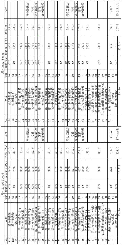
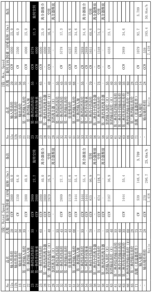
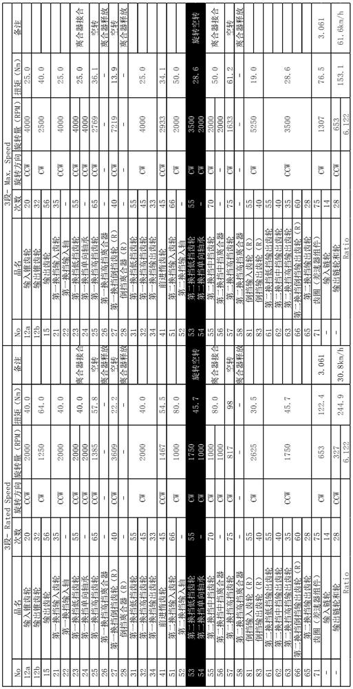
[0027] figure 1 It is a schematic view of a structure according to the present invention. The present invention may include: a first shift input unit 20, a first low-speed shift gear 23 is connected to the first shift input is provided to shaft 22 by shifting the first one-way bearing 24 is constrained in one direction, the first shift input gear 21 integrally provided on the first shift input shaft 22 and receives a driving force from the power input unit 10, a first shift for reverse gear and reverse clutch 27 of the first shift clutch 22 engages the input shaft 28, and a first means for shifting a first input 25 and the first shift gear shifting high gear shaft 22 of the clutch gear engaging high clutch 26 provided at both ends are connected to the input shaft 22 of the first shift; first shift output unit 30, which is a first gear shift lower gear shift input unit 20 receives a first embodiment of the driving force or 25 high shift transmission gear wheel 23 connected to a fi...


PUM


Abstract

The present invention relates to a power transmission device. The purpose of the present invention is to provide a six forward gear and one reverse gear transmission in which shifting between six forward gears and one reverse gear or four forward gears and one reverse gear can be smoothly accomplished using a relatively simple structure. The present invention comprises: a first gear-shift input part which has a reverse clutch and a first gear-shift high gear clutch at respective ends thereof, and to which driving power of a power input part is delivered, the first gear-shift input part being installed such that a first gear-shift low gear is restricted to one direction by a first gear-shift one-way bearing; a first gear-shift output part to which driving power of the first gear-shift input part is delivered; a reverse input gear part to which reverse driving power of the first gear-shift input part is delivered; a second gear-shift input part which has a second gear-shift medium gear clutch at one end, and to which driving power of the first gear-shift output part is delivered, the second gear-shift input part being installed such that a second gear-shift low gear is restricted to one direction by a second gear-shift one-way bearing; a forward idle gear part for delivering the driving power of the first gear-shift output part to the second gear-shift input part, the forward idle gear part being installed so as to be connected to the first gear-shift output part and the second gear-shift input part; and a second gear-shift output part which is installed such that reverse driving power from the reverse input gear part and the forward driving power from the second gear-shift input part are delivered thereto.

Description

technical field [0001] The present invention relates to a power transmission device, which has a simple structure, and realizes the power for shifting between forward 4th gear and reverse 1st gear or forward 6th gear and backward 1st gear by connecting and setting a reverse gear clutch and two or three clutches transfer device. Background technique [0002] Generally, the function of the transmission is to increase or decrease the rotational force of the engine according to the change of the driving state of the mobile device between the input shaft connected to the engine through the clutch and the output shaft connected to the driving wheels, known as the gear transmission, which is used in A pair of gears is selectively connected to multiple sets of gears located between the two shafts to transmit the driving state. [0003] The above-mentioned gear transmission includes a planetary gear set that receives engine power and changes it into an appropriate rotational force f...

Claims


Application Information

Patent Timeline
Patent Type & Authority Applications(China)
IPC IPC(8): F16H3/085F16D11/00F16H3/093
CPCF16H3/093F16H3/10F16H2003/0818F16H2200/0052F16H2200/0043F16H3/085F16D11/00F16D2011/006F16H2003/0938
Inventor 崔亨振
Owner HJ TRANSMISSION CO LTD
Why Eureka
Try Eureka